These pages may not present clearly on some small smartphone screens; please use a normal large screen on a desktop, laptop, or tablet in landscape mode. Thankyou.
© Robin Lovelock.

To see use of the translation flags, and translated subtitles on Youtube videos,
Play Video Here
. Videos only play from English pages.
Sorry if some translation flags below give problems - due to mistakes by Robin, Google, or somewhere in the total internet system.
Probably Robin :-)


Home .
About .
GPS .
Downloads .
Business .
Partners .
Contact .
Family .
AVL .
Links .
History .
AsOnTV .
Holiday .
Covid19 .
Snoopy .
Blog11: Preparing for Snoopy's Robot Boat 2026 Trans-Atlantic Attempt.
(Under Construction - relevant information, as available. Was 2024 ! )
"I always wanted to be an engineer, and now I are one !"
Updated 1945 UK Time ( 1945 Z/GMT/UT/GPS Time ) Sunday 1st February 2026. See near end for "Latest Information in 2026"
Can't scroll to end of this page in less than 2 seconds ? See my
CanUSee page. Get a cheap PC or tablet ? This way you don't miss earlier things ;-)
 You probably reached this "Blog10" page from the
Snoopy page,
or the
Design of Snoopy Sloop page
.
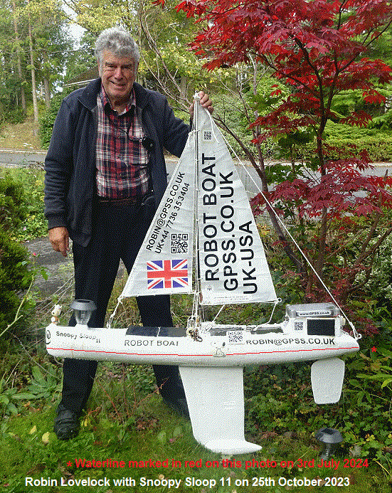
If not, click on a link to know more. Tap or Click on that photo on the right: Snoopy getting close to being ready
- including being marked with a "Waterline" ;-)
Each "blog" page describes detailed work preparing for the next Atlantic Attempt.
i.e. covering a period in the region of a year: less if more than one attempt is made. More if we miss a year, such as 2023.
The Blog pages were started after the first 2012 Attempt, where Snoopy's boat was lost. All later attempts were
with the same boat, sometimes after major repairs. The blogs provide online "Engineering Notebooks",
providing a day-by-day account of repairs, changes, and testing: mostly testing.
- Blog describing background experimental work from 2008 until now.
- BlogX Index to the Robot Boat Blog pages.
- Blog1 from February 2013 until Boat9's October 2013 Atlantic Attempt.
- Blog2 from October 2013 until Boat10's September 2014 Atlantic Attempt.
- Blog3 from Boat10's September 2014 Atlantic Attempt, until the good November 2014 Attempt.
- Blog4 from Boat10's November 2014 Atlantic Attempt, until the March 2015 Attempt.
- Blog5 from Boat10's March 2015 Atlantic Attempt, until the October 2016 Attempt.
- Blog6a" Blog6 Analysis of the October 2016 Attempt (moved from Blog6).
- Blog6" from the October 2016 Attempt until that on 15th December 2017.
- Blog7" from December 2017 until after the June 2019 Attempt.
- Blog8" from after the June 2019 Attempt until the next - in 2022.
- Blog9" Snoopy's 2022 Trans-Atlantic Attempt.
- Blog10" After 2022 Attempt and repair of the boat, until August 2024.
- This "Blog11" - preparing Snoopy's Robot Boat for the 2024 Trans-Atlantic Attempt.
- RB12Blog" How we built Boat 12 from Eric's IOM, including the Picaxe 28X2 Autopilot,
and
Eric's Page.
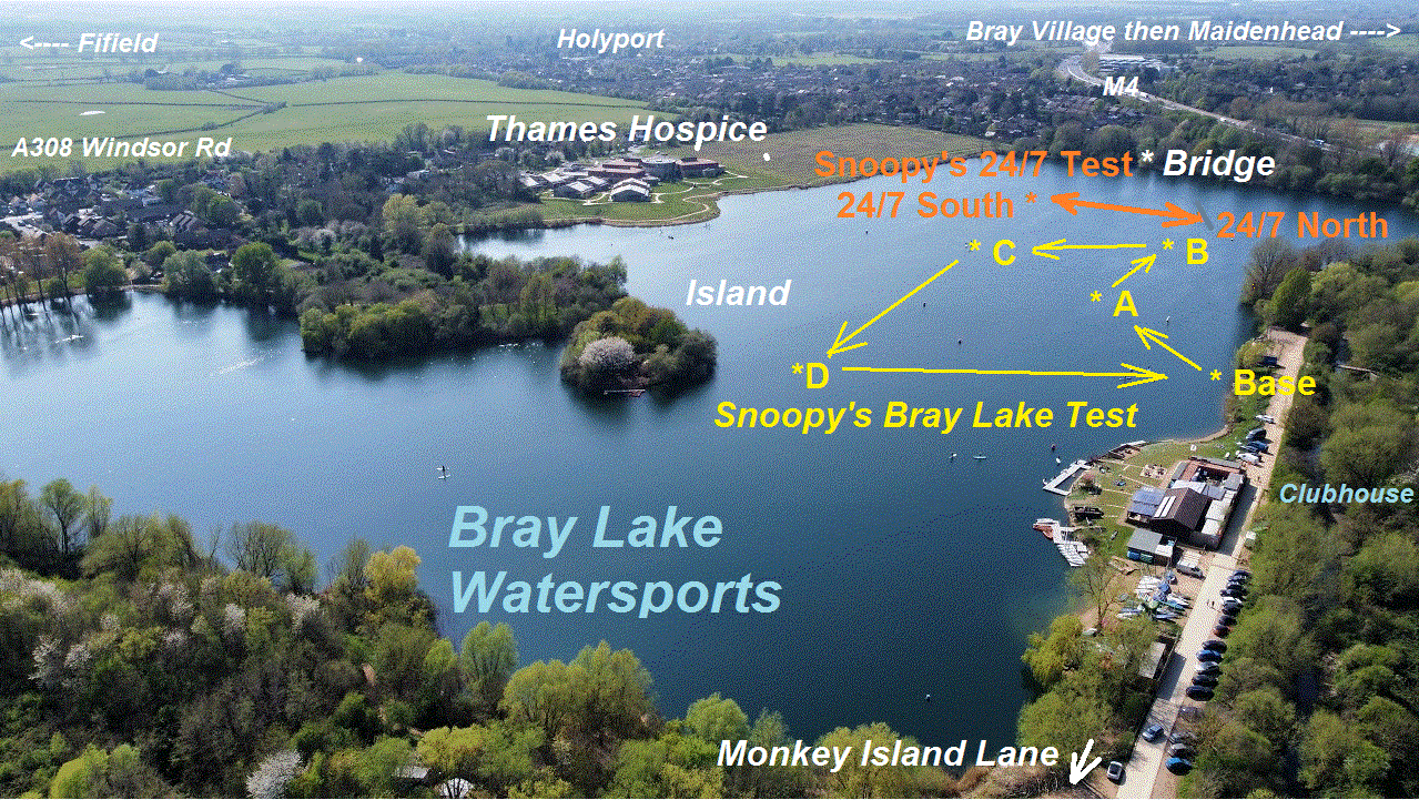
 These blog pages are mostly about numerous repairs to the boat, results from "BRAY LAKE TESTS", or 24/7 reliability testing on Bray Lake.
i.e. Snoopy sailing back and forth over a 24/7 waypoint in "Snoopy Corner". This is typically for several weeks,
in all weather, including gale force winds.
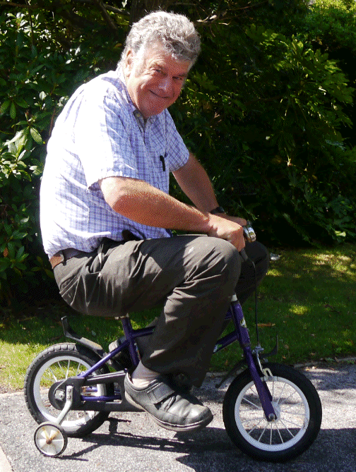
Sometimes, a few things happened which resulted in amusing pictures or stories,
such as countering human-intervention, or testing the wheels for Snoopy's trolly.
Click on the pictures either side for larger versions, or visit earlier blogs above.
BlogX, the "blog of experiments", shows ideas and products, some of which may appear
in future boats.

Starting with near end of
Blog 10 :
May, June, July & August 2024 Updates ...

 from Robin: I hope to add more here soon, but here is a start, in catching up with long-overdue "Work".
i.e. "Doing" and "Documenting" ;-)
Tap or Click on pictures to expand or play a video. You can skip hours to the relevant bit.
Good progress is being made on Snoopy's Robot Boat - See the introduction of the "Early May 2024" video on right :-)
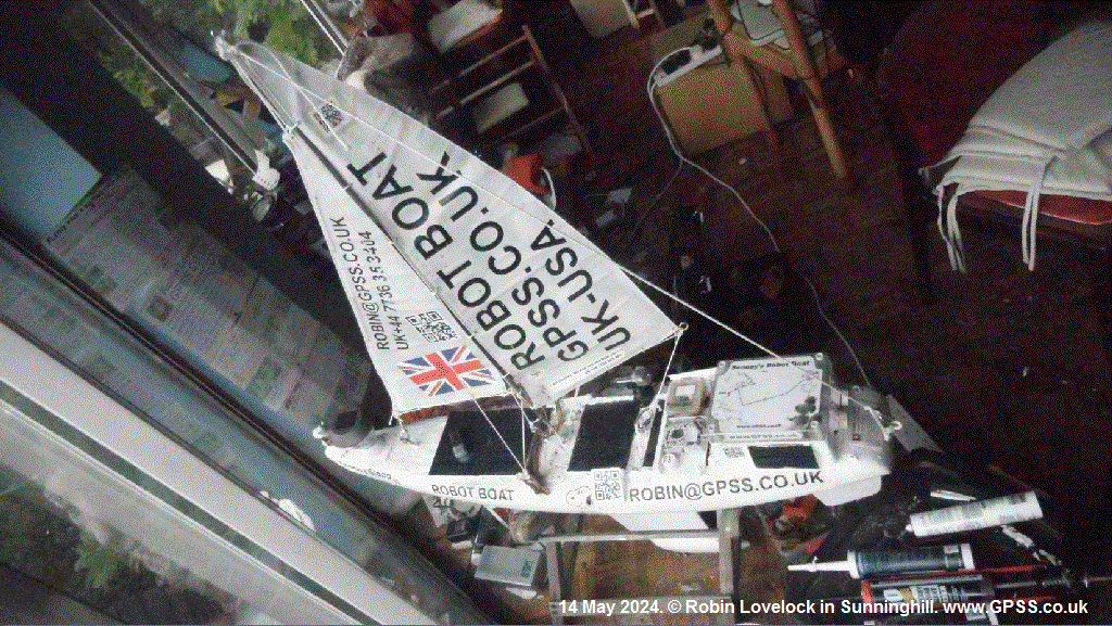
But first, here are some photos taken on 14th May 2024. Tap or Click to expand and see detail.
We may add labels to some of the pictures below, in due course.
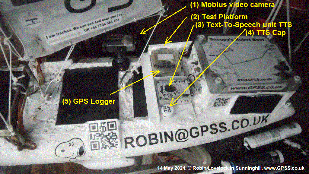
e.g. Test equipment for Bray Lake: 1) Mobius Video camera; 2) Test platform; 3) Text-To-Speech (TTS) unit;
4) TTS Cap - to seal box before going to sea; 5) GPS logger - for detailed second-by-second track of boat
during a Bray Lake Test; 6) small solar panel to top up GPS logger; Maybe other things :-)
Labels added on 19th June :-)

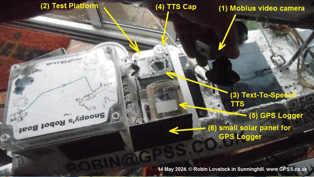

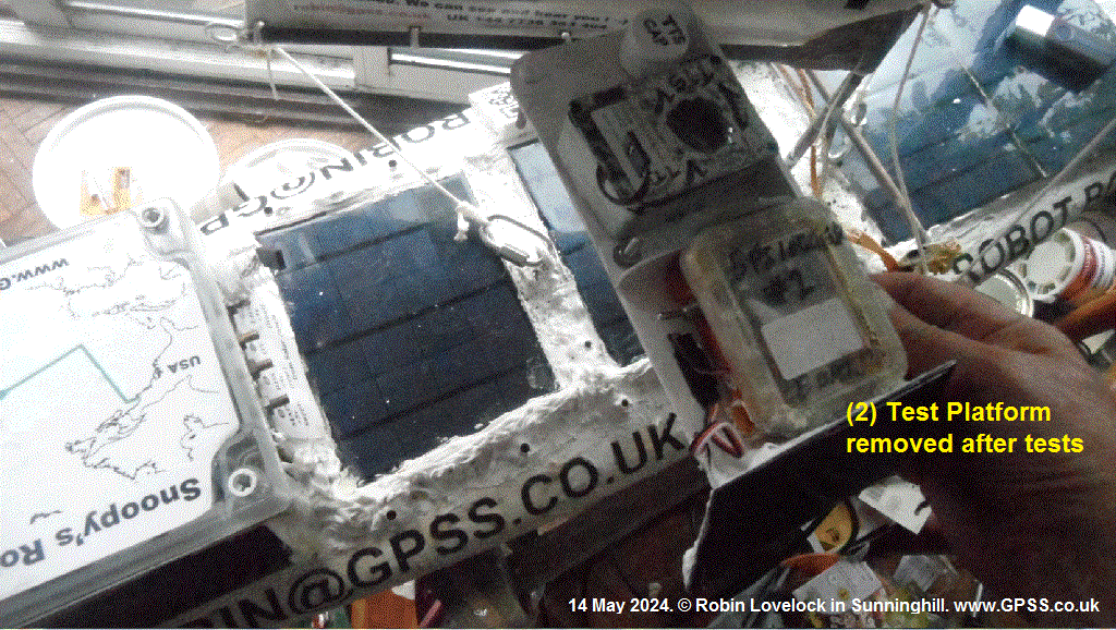
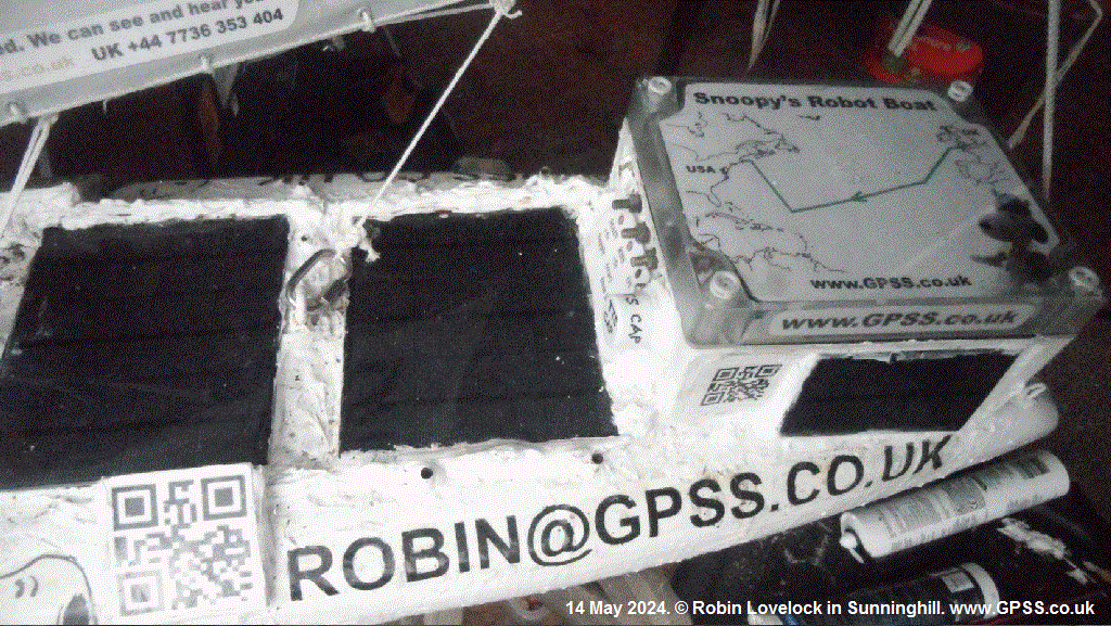
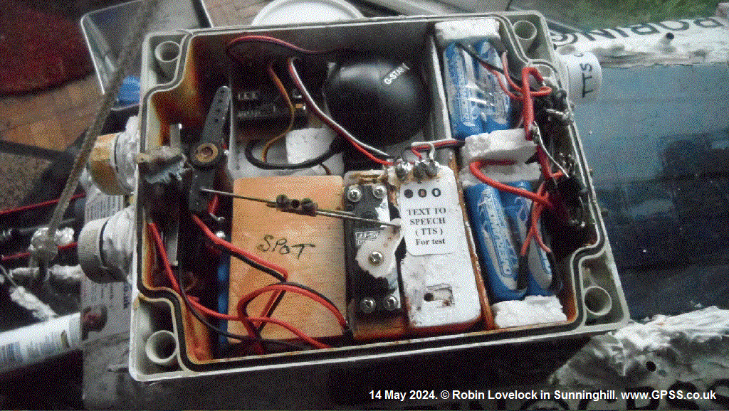

Lots of work was done, in early 2024, by Bray Lake Watersports.
This included chopping back willows that would obstruct the view - but much more.
e.g. Snoopy's "Base", and all of Bray Lake is MUCH better for testing Snoopy :-)



 Saturday 22nd June 2024: Snoopy Sloop 11 is now practically ready for a Bray Lake Test, perhaps preceeded by finding
some water, about 0.5m deep, so that a
plimsoli-line
can be neatly painted on the hull, showing the water level, without
the additional 500 gm of "test Equipment", shown in the labelled photos above, that is just for Bray Lake, and does not go to sea.
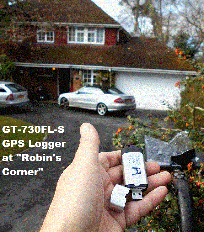
Robin found one working GT-730FL-S GPS logger, from 2019, labelled "B" instead of "A" in this old photo,
and it works ! It fits neatly into the space at the top of the box. The Spot Trace Satcomms tracker can easily be
moved from June's car to it's space in the box.
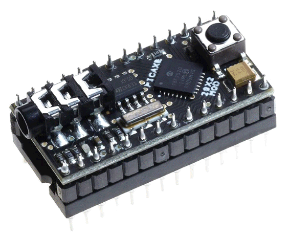 BUT, before the 2024 Atlantic Attempt, Robin would hope that he has at least one tested spare for this GPS Logger product,
and for the Picaxe 28X2 based autopilot. Read my words above, of 27th August and weep ! In short: a LOT of time
can be wasted because of products that have changed or are faulty. Best have several spares before risking losing
it all at sea ! Finding that old, working, Picaxe 28X2 board was critical for the 2024 Attempt. Robin is still
happy to pay someone to deliver working products - but few people are capable - in Robin's opinion ;-)


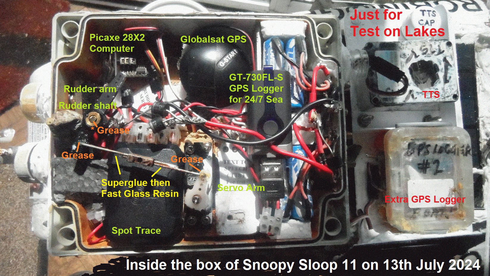
 from Robin on Saturday 13th July: Picture below shows Snoopy's boat completed, other than LOTS of inspection by others,
and a Bray Lake Test - and/or other lakes, depending on things like depth of water, weed, etc. Today I also created a new page,
Team-Joker and put the contents onto the
Snoopy
page, hoping to assist whoever is able to update the Microtransat site. But, that work done yesterday, inside the box:
undoing the grub screw, holding the rudder arm to the steel rudder shaft, gave the hoped for result: the rudder fell out, showing
that I HAD greased it well, many months ago :-) I put plenty more grease on, including where the "push rod" moves inside
the rudder and servo arms. After checking that the rudder was central, the linkage was secured with superglue, then - when dry -
with Fastglass resin. I also instected the soldered joints, including giving several a tug. The Spot Trace Tracker, normally
caried for test in June's car, is now in the box, wedged in with some grey foam. The two power wires, from external
solar powered 5v NiHD batteries, connect to the 4 AA NiMHd cells inside the Spot Trace tracker, via a little terminal block,
with screws well tightened. I do confess that a made a silly mistake, and for a few seconds, the wires were the wrong way around,
resulting in heat and smoke. BUT, this was rapidly fixed, and tests, carrying the boat around, confirmed that Spot was all working.
You can check yourself by tapping or clicking on that image to the right :-)
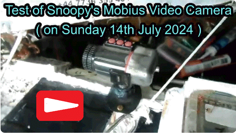
Sunday 14th July:Snoopy's Mobius video camera checked out, including accuracy of time stamp. Tap or Click to play video or expand photo.


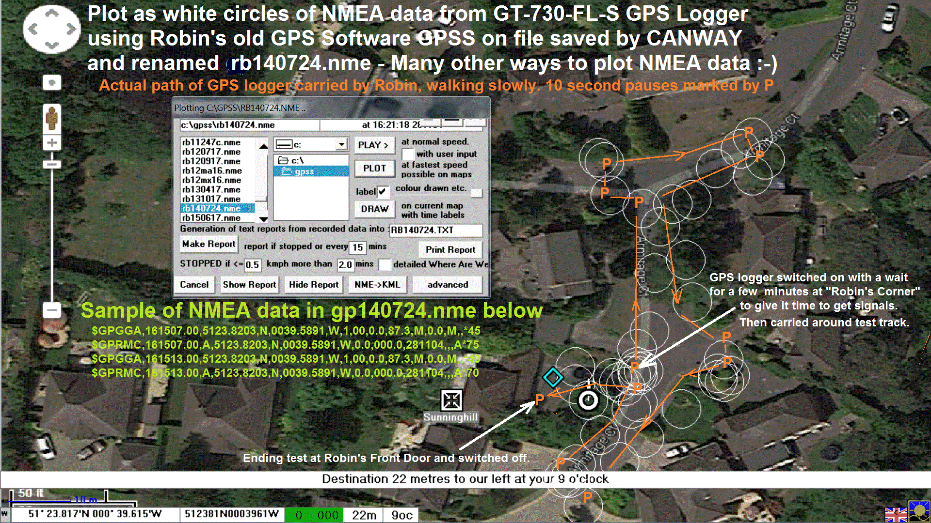 More good progress on testing: the GT-730FL-S GPS Logger, that will stay in Snoopy's boat after it is launched.
Tap or Click on the pictures to expand.
This will be the first time that we are using this GT-730FL-S product, instead of the I-GotU GPS Logger,
used on every Atlantic Attempt since the first in 2012. The I-GotU had become expensive, and this one
seems to be better ;-)
That picture on the left from earlier,
shows unit (A) instead of unit (B) that I found. It was not too difficult to remember how to use it. e.g. switch it on,
to start logging, then off at the end. Then switch it on when plugging it into a PC to download the data into the Canway software.
It is currently set to record positions more rapidly than at sea. We can compare data from it, with that from the GPS logger only
used on Bray Lake, that does not need to run for many days :-)
You may look at the NMEA data as text from
rb140724.nme
or play it on a map with other software or web sites :-)
Here is sample below. e.g. Time 1615 GMT and 7 seconds. Latitude & Longitude. etc, etc :-)
$GPGGA,161507.00,5123.8203,N,0039.5891,W,1,00,0.0,87.3,M,0.0,M,,*45
$GPRMC,161507.00,A,5123.8203,N,0039.5891,W,0.0,000.0,281104,,,A*75
$GPGGA,161513.00,5123.8203,N,0039.5891,W,1,00,0.0,87.3,M,0.0,M,,*40
$GPRMC,161513.00,A,5123.8203,N,0039.5891,W,0.0,000.0,281104,,,A*70

Problems with 5v Power in Snoopy's Box, and with Canway GT-730FL-S GPS Logger ...
Tuesday 6th August 2024:
Problems on two fronts: that GT-730FL-S GPS Logger, and something wrong
with power in Snoopy's box of electronics - being investigated.
But in short: when power is switched on, from the main solar powered 5v supply,
the voltage drops, as if there is a short somewhere. BUT - that GPS Logger ...
The GT-730FL-S was set to record every 1 second, and put on a small solar powered
5v pack*, in the front of June's car, from about 1000 BST ( 0900 GMT / GPS Time )
on 31st July, until about 1700 BST today, 6th August.
The good news is that the Canway software said only 26% of memory used.
The bad news is that very little GPS data was recorded.
For the few interested, the downloaded raw NMEA data, preceded by
an explanation, is in
6aug24a.txt.
* MAYBE the 5v power is dropping ? That would explain the "patchy" recording.
Robin will repeat the test, with a different 5v power source, starting at about 1945 BST today ! :-)

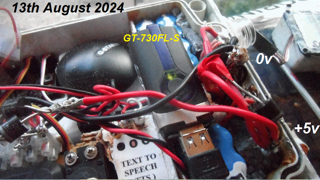 Wednesday 14th August 2024:
Major progress yesterday on that power problem: it was Robin's sloppy soldering of where the two packs
of 5v NiMH batteries receive power from the duplicated arrays of solar panels ! The next "Mid August 2024"
Photo Trail Youtube video will show the nitty gritty work that eventually revealed the problem - hopefully
now fixed ! Tap or Click on picture to enlarge :-)
Sadly, the Canway GT-730FL-S GPS Logger, and it's software, continue to cause Robin confusion.
Despite power on the GPS Logger, for over 7 days, the data Robin saw still seems "patchy".
In an attempt to gather more information, to confirm that the GT-730FL-S GPS Logger hardware,
it's Canway software are OK, Robin has started a different test: cleared the memory, and set it
to record data every 1 minute, instead of every 1 second. This was started at about 1740 BST ( 1640 GMT/UT/GPS Time )
on 14th August 2024. It is known that the date is wrong, but the NMEA GPS Time is a very useful indication
of it is working, and not missing data.
For the very few interested, a sample is in
13aug24a.txt.
Not much data, and just a position wandering a few tens of metres, north-west and south-east,
from roughly where it was - due to poor GPS signals. Date is wrong, but not time - which shows
hours rather than days - in that download.
LOTS of other things happening each week, so Robin can only spend a few hours on the Robot Boat stuff. BUT it looks like we are close to being ready for a Bray Lake Test
- ideally after inspection of the boat by others. The videos, on
www.youtube.com/user/RobinLovelock/videos
,
visible to anyone, is one way of doing it !
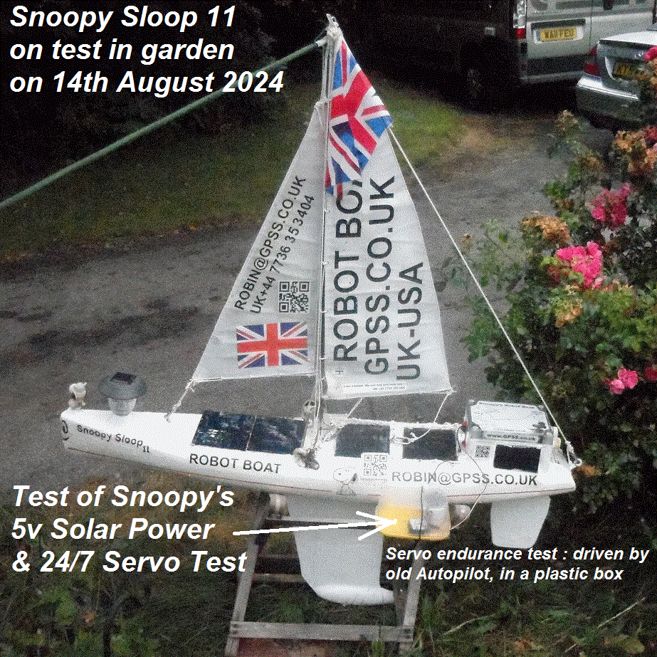 Thursday 15th August 2024:
Good News on testing of servos and the boats's 5v solar power system. Bad News on that Canway GPS Logger. But first the Good News ...
Robin had the bright idea of combining 24/7 testing of the 5v solar power system, with reliabilty testing of servos, of a particular brand, model, and - important - source - particularly
when buying cheap goods off e-bay ! In the past, Robin used a "test rig" of a Picaxe computer, programmed to do typical regular "waggles" of the rudder servo. They would then be left running 24/7,
until the servo failed - maybe not until after 2 or 3 months. Hence the aim of MTBF ( Mean Time Between Failures ) of 2 or 3 months.
The rudder servo has always been the "weak link" in reliability of Snoopy's Robot Boats - other than Robin's silly mistakes, of course :-)
Robin's bright idea was simply to use one of the old Picaxe 28X2 Autopilots, which provides the typical rudder "waggle", but also includes
the GPS, drawing at least as much 5v power as the later Picaxe 28X2 Autopilots. You may just make out the servo, and old autopilot, in that
protective plastic box in this picture. Photo trail videos, to be published as "Mid August 2024" will show much more.
Today it has been cloudy, and Snoopy's 5v solar power supply reads 4.79v at 1645 BST ( 1545 GMT/UT/GPS Time ). The servo is still "waggling" ;-)
Robin's photos & notes say the test was started yesterday evening, indoors, and it read 4.96v. It was put outside, in more light, at about 1100 BST,
and read 4.77v; by 1225 BST it was 4.81v. We will see how it goes ! ;-)
Now the Bad News on Thursday 15th August: Robin still cannot make sense of the NMEA data from the Canway software. Nitty Gritty is in the photos
yet to be published. However, since there are so many doubts about this product, Robin is open to suggestions on a suitable alternative.
He will certainly be searching for a cheap I-GotU - IF he can find it. He obviously COULD make a logger himself, like the one only used on Bray Lake Tests,
but set to record every 1 minute, rather than every second. BUT, Robin would rather "Buy" than "Build", since his time is limited and precious ;-)
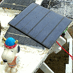 Mixed News on Sunday 18th August:
The good news is that the combined Servo & Power "test rig" proved it's value: Bad News - Snoopy's power dropped to 2.21v by 2140 BST Saturday, and the test rig autopilot stopped.
That was despite bright sky or sunshine, and after only 2.2 days ! :-( Robin has been checking for possible explanations, including him
having made mistakes, in earlier purchases and tests. e.g. today he checked the current, in sunlight, from one of the spare solar panels. He read only 70mA,
whereas the
Design Page ( section "e.5 Better Solar Panels" )
says that the 165x135mm solar panels gave over 500mA (583mA). Hence 4 should be enough for the boat system.
Robin THINKS he would have tested the panels when rebuilding the boat.
A more probably explanation, yet to be checked, is that at least one of the 4.8v 4xAAA NiMH battery packs,
inside the box, had developed a short or electrical leak. e.g. when Robin caused a temporary short during wiring work.
Today he ordered five of this product off Amazon, for delivery tomorrow, for test, and possible use.
Before that, the packs inside the box must be checked. Right now sunlight is being used to gradually charge
the system, which is switched off. At 1615 BST it was 4.55v. The 24/7 test of the servo continues, but with the "test rig" powered
from a seperate 4.8v battery.
from Robin Monday 18th August:
 Best Guess is that, back in 2017, I DID order good 165x135mm solar panels, but when I ordered many more in the past year or two, I DID NOT
DO "ON ARRIVAL" TESTS - particularly on the four put on the boat. To test my guess, I've just ordered the last 5 of smaller, but similar
power vs size, from Amazon for delivery tomorrow. If these deliver more S/C ( Short circuit ) current, that will confirm my guess.
The above is based on my snipping the wires, inside the box, connecting the LHS ( Left Hand Side = rear ) two panels, and checking the (low)
current provided. On the basis that the 4.8v NiMHd 4 x AAA packs might be faulty, I now have a different product under test, that arrived
from Amazon Prime today. First impressions are good: VERY well labelled "Fayerkar Model No FW1-01 BA223030 Rating 4.8v 2800mAh/13.44Wh Ni-MH Battery"
- but, more important, the names and address of factory in Shenzhen, Importer in Belfast, and distributer in London ;-)
One of the Fayerkar packs, fully charged, is now powering the (Servo) Test Rig, since about 1230 BST. The Test Rig seems to draw an average
of about 75mA, so with a capacity of 2800mAh, that's a duration of about 2800 / 75 = 37.3 hours or about 1.5 days. We should see voltage
drop, as the battery exhausts itself. At 1645 BST it's now 4.77v. We shall see ! :-)
 Monday 22nd August:
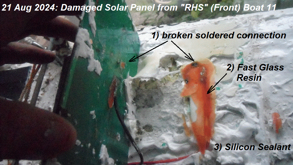 We need to replace at least two, if not all four, of the large solar panels, for the main 5v supply.
Robin was horified when he used a kitchen knife to carefully cut the white silicon sealant, that glues
the panels to the deck. Tap or Click on the picture to enlarge. For those using translation flags,
I've labelled the picture: 21 August 2024: Damaged Solar Panel from "RHS" (Front) Boat 11. 1) broken soldered connection;
2) Fast Glass Resin; 3) Silicon Sealant. He's not sure how it happened, but the brittle hardened resin had come
unstuck from the solar panel board, and taken the blocking diode and wire with it. Maybe that resin is not such
a good idea ! For now he will stick to use of the Wickes white bathroom sealant. Of course, there may be several
faulty bits in the system: he found poorly soldered joints, that just came appart ! Also, those NiMHd batteries,
may need to be changed. Testing is in progress. The good news is that he found a source of what seems to be the correct
product, from what he hopes is a reliable UK distribor. He ordered six solar panels, for delivery via DHL, for delivery
the next day ( today ). The specifications are practically identical to those good palels he discovered in 2017.
The description was "3W 5.5V 540mA Solar Panel 160 x 138 x 2.5mm - 313070001".
The link ( subject to change ) is
Here CPC Seeed Studio Solar panel.
.
The specifications are: "3W Solar Panel; Typical voltage: 5.5V ; Typical current: 540mA ; Open-circuit voltage: 8.2V ;
Maximum load voltage: 6.4V ; Dimensions: 160x138x2.5mm ;
Robin looks forward to "On Arrival Tests" ASAP ;-)

Latest information now in this
Blog11
from 23rd August 2024 on
...

 from Robin on Friday 23rd August 2024:
Blog10
has useful background and detail, but was getting too big and slow to display - so this new
Blog11
was started.
That long photo trail video on the right, has many other topics,
but includes nitty-gritty of work on the boat.
Great News today: those six solar panels arrived via DHL today, and I soon did voltage and short circuit current tests with
both digital and analogue meters. Silly me had not realised what a dramatic increase in power output appeared in full sunlight.
I did the same tests on those panels I'd purchased in recent years, and got the same good result: when the sun came out, from
passing cloud, the current rose quickly from typically 50ma ( 0.05A ) to above 350mA ( 0.35A ) ! :-)
Those two panels at the front, and their wiring, will still need to be replaced, because of the damage found and reported above.
But, for the moment, I'll leave those rear panels as they are, and concentrate on adding NiMHd batteries, wiring, silicon sealant,
and 24/7 static testing of the Snoopy Sloop 11 solar power system, and servos.
By this evening the two front ( "RHS" ) solar panels had been glued neatly in place, using white Wickes bathroom silicon sealant.
This was after a shopping trip to Wickes near Knaphill, with June driving, after she got back from tennis ;-) This sealant is a trusted
product, having beem used on Snoopy's boats for many years, without signs of wear & tear, despite that time on land and sea.
The plan is to use different brands of NiMH battery, for LHS and RHS main power packs. LHS will be a pair of 2300 mAH 4.8v Overlander
4 x AAA NiMH packs, wired in parellel. i.e, 4600 mAH capacity. The RHS will probably* be a pair of the newer product: 4.8v 2800 mAH Fayerkar
4 x AAA NiMH packs. *probably ? The product needs to be tested - already in progress on that "test rig" ;-)
 Saturday 24th August 2024:
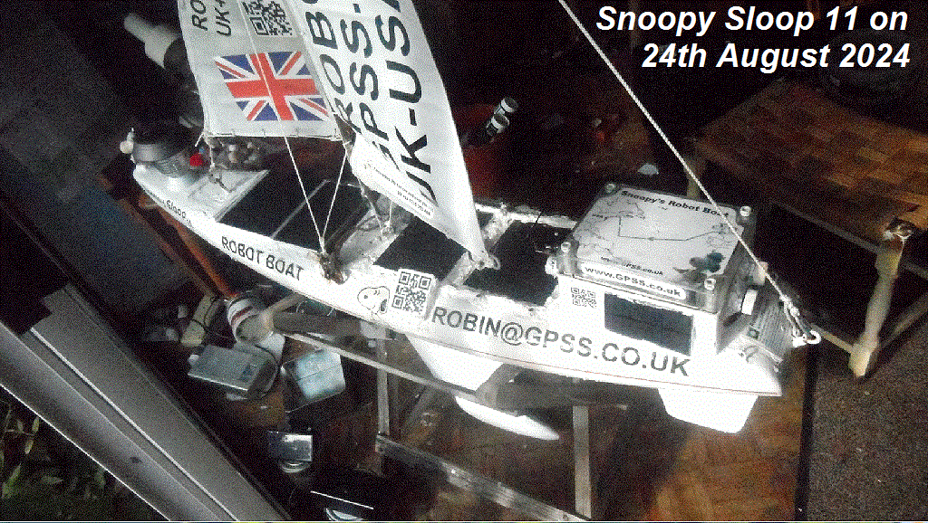
Tap or Click to expand the picture of Snoopy Sloop 11 on the right, taken late today. The two solar panels are "glued" at the front,
with those front corners protected by a bit of wood, screwed & "glued" to the deck, then painted. The important work was installation
of the two packs of NiMHD batteries, described earlier. The "LHS" ( rear ), were charged, since they dropped low when the system
was switched on. Static testing continues on two fronts: the "test rig", swapping recharged packs, and the total boat system itself,
probably to be put outside to catch more sunlight - when the sun is out, not screened by clouds, trees, or buildings ! :-)
Bad news continues on the Canway GT-730-FL-S GPS logger. My paper diary reveals it was set to record every 1 minute, after clearing memory,
at about 1840 BST on 6th August: that a bit less than 18 days, since the Canway software said only 2% of memory used. The good news
is that it MAY record data for 18 x 100 / 2 = 900 days. BUT, the bad news is that I've not been able to see any new data from it :-(
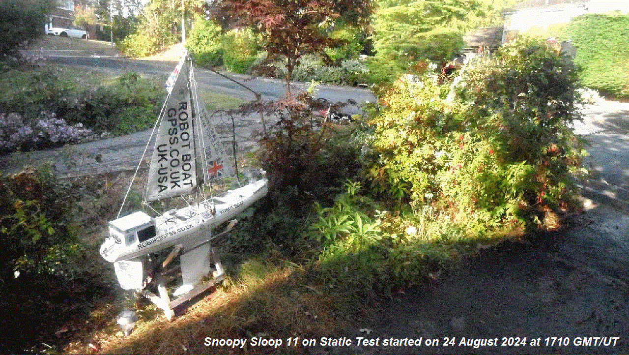 Good News: By 1810 BST ( 1710 GMT/UT), Snoopy Sloop 11 was put on 24/7 static test, in our front garden. It's a good spot for sun, maybe 3 metres west of "Robin's Corner" ;-)
At 1810 BST, voltages at the monitor points read: LHS 5.36v RHS 5.47v Combined 5.47v. The whole boat including sun hitting the panels,
and (random) rudder movement, can be seen clearly on one of our Swann CCTV cameras.
Robin's
Contact
page includes links to Snoopy's SpotT tracker. You will see it has moved. Also our SOS personal trackers.
You can see that we may be away on a family get-together soon - and where ;-)
We will see how the boat system performs under static test.
 Friday 30th August 2024:
Great progress in past few days, using "static test" to uncover & diagnose problems.
The first few minutes of that "Late August 2024" video, on the left, shot yesterday, show you
some important flaws, now fixed.
e.g. today a blown diode, type 10SQ045 was replaced, that linked
the "LHS" batteries and solar panels to the main shared 5v power.
Before that, the boat would only have had half it's solar power capacity
- important as the days get shorther ! Robin is pretty sure he blew the diode,
with a temporary short circuit, some days ago, when checking voltages of
the monitor points, exploting a crocodile clip - which briefly shorted
the system, and blew the diode. But it could also have been done while
doing soldering in difficult conditions :-)
The more dramatic fault,
and one easily remedied, was the servo-rudder linkage rubbing on the
top of the waterproof box.
The Canway GPS Logger problem is still outstanding, and may now get more attention, while we leave the boat on "static test".
 Saturday 7th September 2024:
The first few minutes of the "Into September 2024" video on the right shows Snoopy Sloop 11 on "24/7 Static Test" in our front garden,
and inside the box, with the autopilot running. We are still finding and fixing faults with the 5v solar power system, which SHOULD NOT
drop low enough for the autopilot to stop. Nitty gritty testing and fixing is in the photo trails.
Next things to check on the power system include the current drawn by the Autopilot - particularly by the moving servo - as the voltage
level drops, particularly overnight
Yesterday, I found an I-GotU GPS logger
on ebay, and ordered it for test - and if suitable - for use. It looks promising: an I-Gotu GT-200C. Details are in the photo trail. It arrives in a few days. We shall see ! ;-)
.
 Thursday 12th September 2024:
Static 24/7 Testing is really paying off. Even with hours of sunlight, the boat system power runs flat overnight. Before going into detail,
let's review those words in my old
Design Page
where I wrote
Quote:
POWER CONSUMPTION: The rudder servos chosen draws an average of less than 7 mA, with small spikes during movement. The total electronics including Autopilot computer, Globalsat GPS, SPOT Tracking, is less than 40 or 50mA. This enables use of a small boat with limited deck space for solar panels
Unquote.
This was confirmed by measuring current, with an old moving coil meter,
from a little 5v pack, into the Picaxe 28X2 Computer/GPS/Rudder servo system: typically 50mA.
Let's call it 60mA, and do some simple schoolboy arithmetic: The duplicated power is typically four packs of Overlander 2300 mAH NiMHd batteries.
So, with no solar power at all ( like covering all the solar panels ), the power should last 2300mAH x 4 / 60mA = 153 hours = 153/24 = 6.3 days ! :-)
So testing must continue, to locate things like wiring faults and electrical leakage - including inside batteries.
Today I measured the current consumed by the GPS logger, that SHOULD be wired to be independent of the main power system.
The USB charging circuit into the GT-730-FL-S GPS logger was 120mA ! No big surprise, since why should the designer care about
power drawn when the logger is on charge ? :-)
The I-Gotu GT200-e ordered on e-bay, had arrived several days ago, and that drew 170mA. Conversations have started with the supplier in China,
which will be reported in due course. The important thing is that 24/7 Static tests continue, and to remove doubt, I've unplugged
the Canway GT-730-FL-S from it's USB charging socket inside the box.
 from Robin on Monday 16th September 2024:
Some will find the first few minutes of this latest "Early September 2024" video of use, where I show you inside the box while the autopilot
is restarted. The detailed photo trails are my shared record of the nitty-gritty of testing, such as voltages, and when the autopilot stopped,
after the batteries ran flat - still within hours, rather than days !
Those able to use the Youtube scroll bar, can peruse content, find relevant photos, and identify them with an exact time.
Tests and experiments continue, hoping to solve the power problem, and suggestions are always welcome :-)
 Some may be interested in Friday 13th September 2024, when June, Dick, and myself
were among those attending John Sylvesters lovely funeral service, then get-together. John is the Founder-Member of Team-Joker, when he started
Robin on
The "Microtransat Challenge" Trans-Atlantic Robot Boat
project in 2008. It was lovely to meet John's family, including son James,
who created this public
Page of Photos & Videos remembering John Sylvester
Maybe soon, there will be a link to the video that was played during the service, created by James, with music, and video extracts taken
from
videos you will see on that page above: Dick & John sailing John's boat Joker, from Aberwystwyth, through the Celtic Sea, all the way around
Lands End and to near Southampton - escorted part of the way by a team of dolphins :-) A clip appears from my
video of John demonstrating his Tesla
on my
New Car Page
, and of John and Marion dancing. What a guy ! :-)
 Tap or Click on pictures to expand.
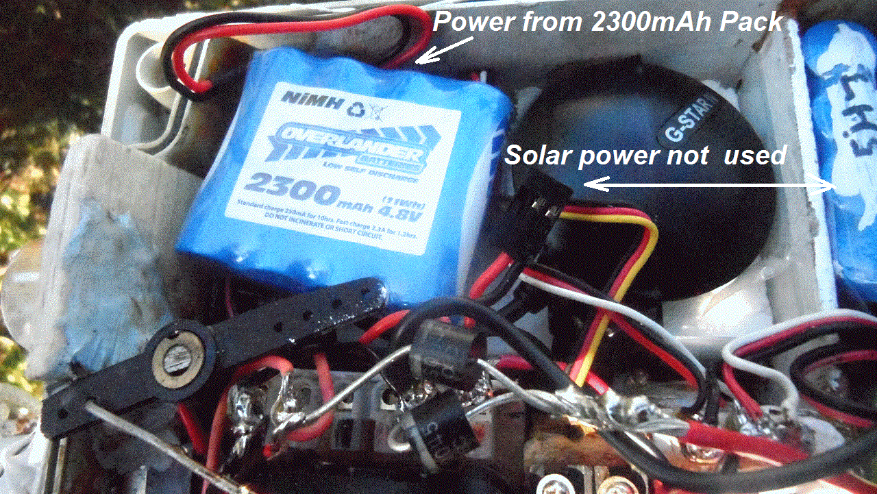
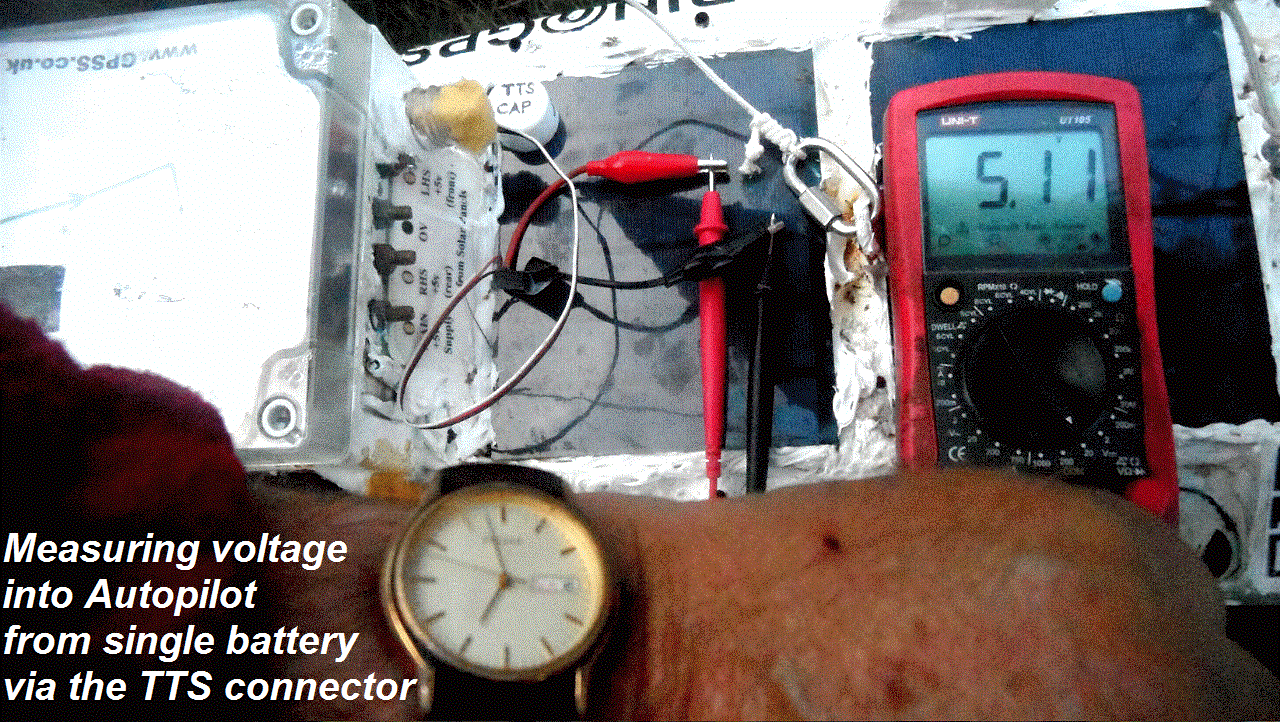
Investigation of the power problem continues, with all power being provided, direct to the Autopilot board,
from a single Overlander 4 AA cell NiMHd pack rated at 2300 mAH. i.e. if supplying 60mA, that should last 2300 / 60 = over 38 hours
= certainly overnight ! :-) Voltage can easily be monitored via a futaba lead, with male plug, plugged in to the TTS female outlet.
The system was set going at 1555 BST today Monday, and measured 5.33v running. By 1625, 0.5 hour later, voltage had dropped to 5.14v.
By 1855 BST it had dropped to 5.10v. That's a drop of 0.23v / hour. At that rate, we can expect the autopilot to stop within 4 or 5 hours.
e.g. below 4v in less than 5 hours = midnight.
Late evening update:Voltage still 5.01v at 2230, so that's only dropping 0.05 volts / hour. So another 20 hours before below 4v ?
Looking good. We shall see in the morning if this test bears fruit ;-)
 Wednesday 18th September 2024:
The test DID bear fruit: it showed that single 2300 mAH pack has the capacity to keep the autopilot system running for over a day, even without
any solar power input. CCTV showed the rudder stopped at 2130 BST yesterday, Tuesday 17th September. By 2230 voltage was just 2.12v. So, looking
at when this test was started, at 1555 Monday, that's over 29.5 hours - and the pack had not been freshly charged.
The next test started was to remove the extra battery, and connect the output of the "LHS" solar power, directly to the Autopilot board,
measuring voltage via the TTS lead as before - but there is also that "LHS" brass bolt monitor point. This test was started at 1115 BST today,
with LHS voltage at 5.4v. At 1215 it was 5.36v and by 1520 was 5.29v. i.e. dropped 0.07v in 3.1 hours, so MAYBE dropping 0.07v/3.1h = 0.022v/hour ?
i.e. good for at least 60 hours, if we take 4v as minimum ? BUT, remember this should be twice the capacity of that single packe, AND, it has those
two "LHS" (front) solar panels, charging when the sun is out. I just checked at 1600 BST: 5.29v; then at 1900: 5.12v - not that much lower - yet :-)
We shall see how this test goes, overnight, and can then consider a similar test, but only using the "RHS" (rear) batteries and solar panels.
We can also be thinking about whatever other tests and checks to do, to see why the combination of LHS and RHS via diodes, wiring,
and switches, gave problems. Probably my silly mistakes somewhere - but where ? :-)
 Saturday 21st September 2024:
A detailed "Mid September" video should be
published tomorrow, Sunday, but don't get lost in the nitty-gritty of that, before reading and understanding this blog11 page ;-)
That earlier "Duck Mk3 on Black Park Lake" video, on the right, is relevant, since the "Mid September" video includes an important visit to Black Park Lake,
to chat to wise old model boaters. I was hoping to be accompanied by Richard, so he might heed their advice, on things like batteries
for his boat. I've often found it useful, for many decades, to use others to give good advice. e.g.
AsOnTV page ;-)
In short: 24/7 static tests continue, are proving worthwhile. e.g. that test above, started 1115 BST Wednesday, with LHS double pack, ran until
the autopilot ran out of power at 0200 BST Thursday: after only 14.2 hours ! Far less than 2 x 2300mAH capacity / 50mA current drawn = 92 hours > 3 days expected.
Numerous tests were done, and still being done, with batteries and the total Robot Boat system. One suggestion by friends is that perhaps
one should not connect those NiMHd packs in parallel. Google
"can NiMd batteries be connected in parallel ?" and you get
"They're safe to run parallel. Just make sure all are at same charge before connecting."
It confirms that OK - IF they are the same brand ( and product and batch ) !
But remember my earlier words: things like batteries may have been damaged by my earlier silly mistakes :-)
No time for working on finding a suitable GPS logger :-(
 Sunday 22nd September 2024:
Here is that promised "Mid September 2024" video, that had me waking up in the middle of the night to check :-)
I must admit I was impressed by Youtube ( Guys ? ) choice of "title picture", of the many thousand in the video,
and what you see if you hover over it. I must show these guys if I see them in the Sunninghill Comrades Club tonight :-)
But, despite the many other topics covered by the video, I hope a few of you will find some bits of interest.
Maybe I'll add more words here, after I had a few more hours sleep. I am very aware that some of you are
in very different time zones, that span the globe from USA to Australia. Thanks for your visits to this page and your help :-)
 1400 BST Sunday:
Got enough sleep and good news: the Overlander "LHS" double pack, connected normally, is holding voltage at 4.81v, at 1320 and 1340,
after 24 hours of being connected, at 1340 BST yesterday. Then it was 5.3v, combined LHS and RHS (not there) through diodes.
There had been some sun on the boat, sat near the window, Saturday, but not though the night, and today it is cloudy.
I will not distract you with poor results of other batteries, that are in those photo trail videos ;-)
We will continue this test, hoping this pack does it's job, then consider what next. e.g. add the "RHS" double pack ? :-)
Monday 23rd September 2024:
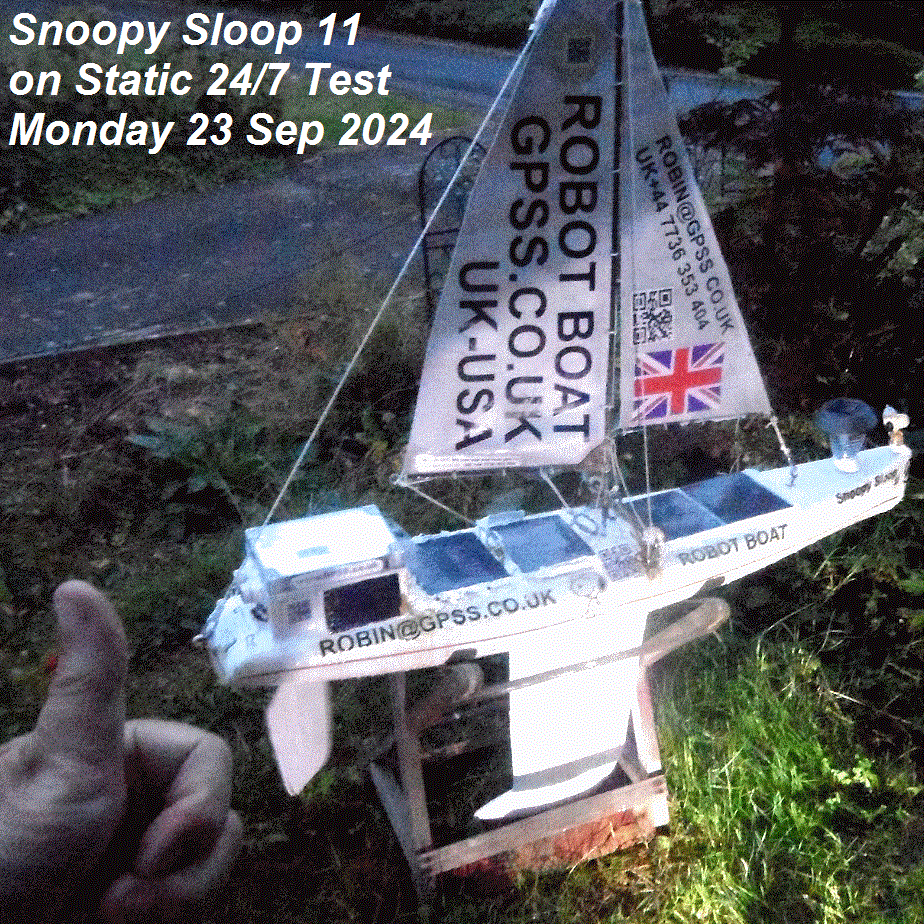
Good results with voltage levels, and the boat was put outside, by 1400 BST, in cloudy skies, to see if the solar power system copes.
This was after adding the newly arrived pack of four sub-c NiMD cells, on the RHS: Overlander "Tornado 3300" mAH.
At 1400 monitor point voltages read: LHS 5.00v RHS 5.01v -> combined 4.77v. At 1530, 1.5 hour later, this was
LHS 5.08v RHS 5.09v -> combined 4.85v. i.e. climbing nicely - without sunshine :-) At 1705 LHS 5.06v RHS 5.06v -> 4.83v.
Still looking good. We shall see if the power is OK, in the hours & days ahead :-)
Major tidy up done to the
Snoopy page.
At 1905 LHS 4.98v RHS 4.98v -> 4.74v. Still OK.
Tap or Click on picture to expand to larger photo.
Tuesday 24th September 2024:
Still good. At 0950 LHS 4.9v RHS 4.9v -> 4.65v.
Brighter sky and at 1505 LHS 5.13v RHS 5.15v -> 4.91v.
Hobbies overlap. Tonight is the
FAST Presentation on TSR2 on 60th Anniversary of it's first flight
. See also
EASAMS and
track us
to Farnborough if you wish :-)
 Friday 27th September 2024:
For the very few interested, and able to use the Youtube time bar to peruse content, here are the photo trails of days that
included events such as that FAST Presentation on TSR2, and pub lunch with Grumpy Old Men, some of whom have knowledge on
many topics, including TSR2, high technology over many decades, and robot boats. David Sammon met some of Robin's friends :-)
 The nitty gritty of Snoopy Sloop 11 24/7 static testing is in the video, including fact that the solar power system,
and total boat system, is coping well.
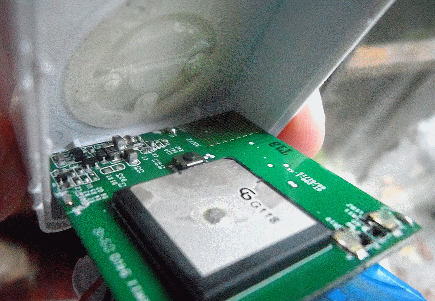
Attention is now being put on problems of getting a GPS logger to work,
and today, Friday, that I-GotU was pulled appart, without damaging it. Here is just one, of many photos shot today,
and to be published in due course ;-) Tap or Click on the picture to expand.
Photos show that, although there is doubt about the build quality of the product being tested, it does at least contain the
required bits like battery, GPS, circuit card, and switch. Although there is doubt if the plastic button hits the switch.
Robin made contact with the supplier in China, probably west of Shanghai, some days ago, but English/Chinese translation software
might be an obsticle. Meanwhile, Robin is happy to buy any suitable GPS logger, that has been TESTED. It saves time ;-)
 Saturday 28th September 2024:
Progress on GPS Logger: Stupid Robin had tried to use the wrong software ! We should use "Sports Analyzer" for the I-Gotu GT200-e.
"Canway" (Travel Tracker) is for that other Canway GT-730-FL-S GPS Logger !
Sunny today, so the sun may charge the solar powered batteries more fully.
More progress to report here soon, I hope :-)
1700 update:
Nitty gritty of the GPS Logger work, mostly unsuccessful tests, will be published, in a few days, in the "End September" video,
but, in summary, whatever PC I plugged the I-GotU into, including Windows 7, Windows XP, and Chrome, the USB com port did not appear.
I do recall it appearing on one of my platforms. No visits by anyone to this page, including from China, or my mates sending me emails,
where my polite reply is to look at this page, and why: see visitors below :-)
 24/7 Static Testing of Snoopy Sloop 11 continues to bear fruit. e.g. if the power runs too low, due to lack of sun for days,
the autopilot stops, but with the rudder servo in a "hard anti-clockwise" (rudder left) position. This may be stalling the servo,
causing far more current drain, and stopping power recovery, even after good sunlight. This has been known about for years,
and why I added the mechanical "rudder stops" - to stop the rudder linkage flipping right over, if the batteries run flat.
When this happens now, on static testing, I simply switch off the power, for a time as short as 30 minutes, to give the batteries
a chance to charge from the solar panels, before the boat is switched on again. Here is some data from those photo trails,
yet to be published: Boat stopped yesterday, at about 1850 BST; today, despite sunlight, by 1115 BST voltages were only 2.36v,2.40v->2.12v.
By 1430 BST these had dropped further to 2.33v, 2.37v ->2.09v ! Boat was switched off at about 1440, but back on 30 minutes later,
by which time, voltages had climbed to 4.87v, 5.97v -> 4.61v (after switching on). By 1605, with boat on, voltages were
4.55v, 4.59v ->4.32v (dropping 0.3v - but shady. BUT, I just checked voltages, since the sun has been hitting the boat:
4.92v, 5.80v -> 4.68v. i.e. RISEN by 0.36v ! I'll keep the boat where it is, in partial shade from our oak tree, since
it is a tougher static test ! :-) Tap or Click on that July picture on right, to see bits like the servo linkage and rudder stops.
1915 Saturday update:
More useful information gathered: this time the rudder stopped hard RIGHT ( servo anti-clockwise ) on the other (plastic) "stop".
CCTV showed this happened at 1755 BST. Voltages measured just now at 1845 BST were: 2.36v, 2.37v -> 2.15v. As an experiment,
to see what happens, as it gets light tomorrow, I've manually moved the servo to it's centre ( straight ahead ) position.
The system remains switched ON. It's possible that this will make no difference, but clearly the servo is NOT now in a "stalled" position.
We have ever measured total current drawn from a LOWER voltage supply. e.g. 2.5v instead of 5v. Not difficult :-)
I wonder if there is a SIMPLE current limiter, or automatic cut off switch, for when voltage drops too low ? BUT it must be RELIABLE
and SIMPLE ;-)
 2100 Saturday update:
LOTS of photos of my messing around trying to get Travel Tracker software to connect with the I-Gotu GT200-e without success.
Root problem seems to be that it relies on a Microsoft driver, which Microsoft no longer support. BUT maybe there are some guys
out there who can fix this problem. If so, it means anyone selling I-GotU products will benifit ;-) Meanwhile, I have to
keep all options open. I just want to buy a working and tested GPS Logger product. Let's hope I don't have to resort to making it myself,
based on those GPS loggers used on Bray Lake. Better to pay someone else to do it for me ;-)
Still no visitors to this page other than me, today. Useful information for me ;-)
 Sunday 29th September 2024:
More progress: communication with "Saint Surplus", supplier of that I-Gotu, may be published when there is something to say. I still
welcome suggestions on other alternative GPS Logger solutions.
Meanwhile,
tests have started which indicate the power problems, due to a "stalled servo", might be fixed with something as simple as
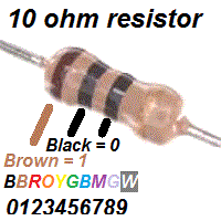
one or two 10 ohm resistors, in series with the 5v Futaba-compatible power lead, from Autopilot into servo. Some of you
may enjoy going back to school day electronics and arithmetic :-) Tap or Click on that picture on the right that may help,
regarding the industry-standard colour coding of resistors. But first the simple tests, measuring the current drawn by my
"servo test rig". As expected, when the autopilot is running, it draws typically 60mA (0.06A), spiking much higher when the servo
moves. If I hold the servo arm, current may rise to much higher - perhaps 0.6A. Years ago I added mechanical rudder stops,
because, when the power ran low, the servo tended to keep moving clockwise or anticlockwise, risking "flipping" the
mechanical linkage, between servo and rudder. That screwed up the steering from that point on. So simple schoolboy Ohms Law
says that Ohms = volts / amps. Or Volts = Ohms x Amps. e.g. if 10 ohms in series, just the servo voltage would drop only
0.6v normally, or 6v if stalled. BUT the answer is to TEST it. I've order a batch of 10 ohm resistors on Amazon, for deliver
by 1300 tomorrow Monday. Why ? I wasted too much time looking in my heaps of junk - in the queue to be sorted.
Now that schoolboy stuff about remembering the resistor colour code. See the picture. At school, in the early 1960s, I was taught how to remember it:
"Bye Bye Rosie, Off You Go, Bye Manchester's Great Western" :-) i.e. Black (0), Brown (1), Red (2), Orange (3), Yellow (4), Green (5)
, Blue (6), Mauve (7), Grey (8), White (9) :-)
 I'm curious what engineers, or just school kids,
are taught in other countries :-)
At 1915 BST, in darkness, the autopilot was still running - just ! Voltages were 4.17v, 0.76v ! -> 3.99v. i.e. We can expect it to stop soon.
See how much lower the RHS is, at ~ 0.76v, and probably because that larger capacity pack needs more time to charge fully.
Hopefully, tomorrow, we can try out that "servo resistor" idea, and maybe result in better 24/7 power performance. We shall see :-)
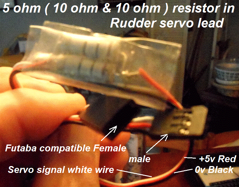 Tuesday 1st October 2024:
The
End of September 2024 Video
, on the left, includes the nitty-gritty of this work, but the first few minutes of introduction should be of great value in
seeing latest news about Snoopy's Robot Boat. The "Jury is still out" on that resistor idea. Next tests will probably include
starting with a more fully charged set of batteries, and maybe trying 5 ohm instead of 10 ohms. School boy stuff again:
another 10 ohm resistor, in parallel, across the other ? :-)
Tap or Click on that picture on the right to read details. I hope to put it in the boat soon, checking voltages,
and switching the boat on.
 Thanks Richard for those bright ideas about servos, but not bothering to look at this page - it would save
both of us so much time ;-) But it's worth me mentioning some here, since it will remind guys out there
that I've thought about some of these things. e.g. different servos ? micro switches on servo end stops ?
Lots more - but remember - any change must be thoroughly TESTED, and the total system must be RELIABLE.
LOTS of R & D work has been done since 2008, documented in those
Snoopy Sloop Blogs
! :-)
I am reminded of my dear late friend John Sylvester, who, in the early years after he got me started on Microtransat,
in 2008, would pop in each day for coffee and brainstorm the design of what became Snoopy's Robot Boats.
John got me started, and the best idea he had was a "GPS Only" autopilot, without a compass. However,
being a chemist, teacher, and lateral thinker, rather than an engineer, he also had some pretty crazy ideas. e.g. don't use
a rudder, but shift weight from side to side to steer the boat :-) Make the boat as long as possible,
based on that equation of a boat plowing through the water. Smaller and lighter is better - in my not so humble opinion :-)
Tap or Click on John to visit the
Page of Photos & Videos remembering John Sylvester
. Sleep Well John :-)
Rain is delaying work on boat. I watch
Metoradar Rain prediction for Sunninghill
looking for a pause. This Swiss based site covers the whole World. BUT, remember the military importance of this, before you trust it too much ;-)
For relevant weather predictions, see the
Snoopy
page ;-)

 Update after 1845 Tuesday 1st October 2024:
In short: the 5 ohm resistance was a disaster ! Lots of photos were taken for a future photo trail video, such as "Into October 2024".
When the rain eased off, the boat was brought in, into the dry, at about 1730 BST, to make it easier to work on, and take photos. Combined voltage was about 5v,
and when the power was switched on, after the 5 ohm resistance was inserted, between Picaxe computer and servo, the servo went crazy !
Even waiting minutes, it simply randomly waggled. The voltages also dropped a little, to 5.31v, 5.24v -> 5.0v. At about 1855 BST.
There was a pause, for Robin to listen to the sad Radio 4 News, with relevant photos taken from his
Grumpy
page, then the boat was put back outside on 24/7 static test, with it's normal direct connection of computer to servo.
The 5 ohm resistor cable was put onto the Servo Test Rig, in the Games Room, and that worked OK - for now !
Richard asking "what type of Servo ?" made me realise that this important information is tucked away in photo trails,
Blog Pages
- particularly
BlogX Page
.
The
Design Page
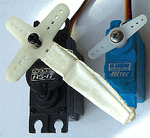
may need updating with this picture of the Futaba S3003 servo, currently being tested in Boat and Test Rig.
Tap or Click on pictures to expand or visit the relevant page. e.g. help, years ago, from Cesar in Romania. Then - more importantly - Peter of Team-Joker,
in comparing the ASR-17 and HS5086 servos, and use of our servo test rig software, to test servos to death ! :-)
Why is this subject important ? Because our tested products like the AComms ASR-17 are difficult to find. Even good products become "Obsolete",
making my old mantra about buying spares important !

 Update on Wednesday 2nd October 2024:
A bit more on that "schoolboy electronics stuff: I said earlier how I was curious how guys, in other countries, remembered resistor color codes.
A quick google search immediately found it - for Americans. We English spell "colour" as "colour"; the Americans as "color".
To remind you, at school I learnt: "Bye Bye Rosie, Off You Go, Bye Manchester's Great Western".
Here is what Google found:
QUOTE
Here are some other mnemonics for remembering resistor color codes:
"Betty Brown Runs Over Your Garden But Violet Gingerly Walks"
"Bad Bears Raid Our Yummy Grub But Veto Grey Waffles"
"Bill Brown Realized Only Yesterday Good Boys Value Good Work"
UNQUOTE
I guess guys in many countries speak American English. e.g. if you google translate "bullshit" in Russian, it displays "bullshit" :-)
It may seem like a distraction, but it's all about communication, and use of automatic translation. Try those flags at the top ;-)
As I was Writing these words, I was interrupted by a 'phone call from Roy, of Team-Joker, to say that a trans-Atlantic boat was appearing on BBC TV South now.
BBC TV South broadcast
Snoopy's 2012 first Atlantic Attempt in 2012
, Live.
I watched and took photos of today's TV broadcast. Tap or Click on the picture to visit that old,
but very relevant,
Toy Boat page
:-)
 Progress today ? Photos taken, for the next "Into October" photo trail, showing details. But, in summary, the boat
seems to power up and start working, after even minutes, rather than hours of sunlight. It has been rainy and cloudy,
and that big oak tree does not help, but at least the "24/7 Static Test" is more demanding of the power system.
No help yet on things like a solution for the GPS logger :-(
from Robin Lovelock on Saturday 5th October 2024:
Play at least the first few minutes of this
Into October 2024 Photo Trail Video
to see the latest news of Snoopy's Robot Boat.
In short: it seems the power system will cope,
but we need to continue 24/7 Static Testing with at least
a few hours of sunlight on one day.
The photo trails show the nitty-gritty of things like times and solar power voltages,
and when the autopilot stops, but then restarts after even less than an hour of imperfect sunlight.
The photo trails, with voice commentry - with automatic subtitles and translation - show other overlapping information.
e.g. how few, and who, look at this page - even if only to look at the top to see if this page has been updated
since they last looked at it ! :-)
Many Thanks to those who do, including over many years, and who provide expert help in many ways, including,
not just the boat, but how we communicate between ourselves: over the Net and/or Face-to-Face :-)
after 1730 BST Saturday update:
Here is some data that, in photos, not yet published in a video:
Last Friday night, the boat's autopilot stopped, at about 1900 BST. At about 1010 BST today, Saturday, the boat started again -
after about 15 hours of inaction. This re-starting was after hours of daylight, including less than 30 minutes of direct sunlight,
that hit the boat after about 0945 BST. Voltages were measured, much later as follows:
LHS 4.91v; RHS 4.92v -> combined 4.66v at 1700 BST. We will see how many hours the boat works for tonight. Shuts down for less than 15 hours ?
Ideally, it should not shut down at all :-)

 Sunday 6th October 2024:
It DID shut down - at about 1820 BST Saturday ! Details will be published in due course. It was wet and cloudy today, but, other than a brief "twitch"
at 0955 this morning, it remained dead, until I made changes to follow here. Voltages were LHS 2.34v, RHS 2.41v -> 2.12v at 1515 BST.
Bright idea: add external power to charge system, starting with LHS. Boat was switched OFF at 1545 - which also helps - see above.
Then, that 5 ohm resistor lead was connected to a seperate 5v battery, via Futaba leads, to crocodile clips, to go onto the 0v and LHS
brass bolts monitor points. The voltage could be seen to be climbing quickly in seconds ... 4.07v,4.09v,4.11v etc.
By 1630 ( 45 minutes later ), the voltage had climbed to 4.60v, 4.20v ->4.58v and I switched the boat back ON. The autopilot soon started
waggling the rudder, and voltages were: 3.89v, 3.81v ->3.70v at 1630 BST. I am not optomistic how long it will run,
because it is still overcast.
It stopped within 10 minutes, by 1639. Voltage had dropped to only 1.72v, 0.35v -> 0.95v by 1830 ! It was switched OFF and the external battery removed.
Monday 7th October 2024:
The boat was switched ON again, after some sunshine, and here is the data, recorded on photos: 5.34v, 5.77v -> 5.32v at 1540 BST,
before switching on. Immediately after ON, 5.32v, 5.83v -> 5.09v.
In less than an hour, voltages had dropped: 5.26v, 5.25v -> 5.02v at 1630 BST.
Let's see if it survives the night ! :-)

 Tuesday 8th October 2024:
The boat stopped at 2335 BST yesterday - after less than 8 hours :-| It was given time to recharge from sunlight, then switched on at 1540 BST today.
It ran OK until stopping at 1754 BST. Just 2.22 hours ! :-|
But before I go into detail, about voltages, times, etc, let me say a few words about the sort of guys out there who can "think laterally".
If you Tap or Click on that picture on the right, it is what I got when I searched for "Famous people with Autism".
Not bad to be compared with Albert Einstein and Isaac Newton eh ? I know several guys who have this, and can be admired.
In my opinion, one of these may be Aleksey on
Aleksey's Sailing Saucer
page, but, now he is less interested in robot boats as he is in wildlife: a bit like Chris Packam.
I say this because I often get good ideas from almost anyone. e.g. today,
at coffee after Pub Lunch, Richard suggested how that rudder servo might be protected by a simple
inserted module, between computer, and servo. BUT, not a 5 ohm resistor, but a digital circuit
that swiches power off, if the current drawn is above a particular threshold ( 60mA ? ) for longer
than a particular time ( 1 second ? ). But then switches power back on, after a diffrent time has elapsed ( 5 minutes = 300 seconds ? ).
The result should be a massive reduction of that average "stalled servo" current. BUT, someone has to find, or prototype the module ;-)
Now some of that data, with more detail in due course: At 1044 BST boat still switched off was 5.26v, 5.83v ->5.27v.
It was switched ON at 1540 BST, when seen to be 5.34v, 5.77v ->5.32v which soon changed to 5.32v, 5.83v -> 5.82v with system running.
As mentioned earlier, the autopilot stopped at 1754, after just 2.22 hours. The boat was left switched ON, to gather information.


 Wednesday 9th October 2024:
Minor but important changes were made to the very top of
Robin's PRESS Page
of overlapping topics, many of which are directly,
or indirectly related to Snoopy's Robot boat.
Some relate to products, used in the boats,
and even that UK DVLA one, UPDATED TODAY, effects Snoopy's transport to the coast.
Many topics are, of course, far more important, across the World.
But now some nitty-gritty of new data: the boat stopped, for about 15.7 hours, until it re-started at about 0940 BST today,
with cloudy sky. Voltages were measured in the afternoon as: 5.05v, 5.11v -> 4.83v at 1520 BST. It is still cloudy,
and occasionally bright.
The boat stopped at 1801 BST, which after 0940, is about 8.3 hours working ! If we sort that "stalled servo" problem,
we MAY be able to get it to run 24/7 ! :-)


 Thursday 10th October 2024:
No change in important conclusions so far, such as need for help with things like finding or building that "current limiter", in series with the rudder servo,
to stop the massive power drain, when voltages stops, and the servo pushes against those "rudder stops". But here's some basic data:
after a brief "twitch" at 0930 BST, the boat started properly at 1444 BST. That means it stopped again overnight for about 15.5 hours
- not much different to yesterday's 15.7 hours ! The boat stopped at 1727, which is less than 3.3 hours since it restarted at 1444.
NOT GOOD compared with 8.3 hours yesterday ! Do not forget that it should not stop at all !
Lots of other, sometimes related, things happening, and I am editing the "Early October 2024"
photo trail video, for processing overnight, and upload to Youtube sometime tomorrow Friday ;-)
 Friday 11th October 2024:
Play at least the introduction of the
Early October 2024 video
:-)
It looks very sunny, with clear sky, today ! :-) CCTV showed the boat restarted at 1012 BST: 16.7 hours off since 1727 - MORE than yesterday's 15.5 hours.
This afternoon, in partial sunlight, voltages were 5.02v, 5.73v -> 4.80v at 1435 BST.
The boat stopped at 1710 BST: just 7 hours running, LESS than the 8.3 hours last Wednesday 9th. It's not obvious why ???
No change: we need help with that "servo current limiter"
and things in the video, like "property maintenance", coping with poor health, and helping guys enjoy life while they can ;-)
 Saturday 12th October 2024:
Thanks to Buzby on the
Picaxe Forum
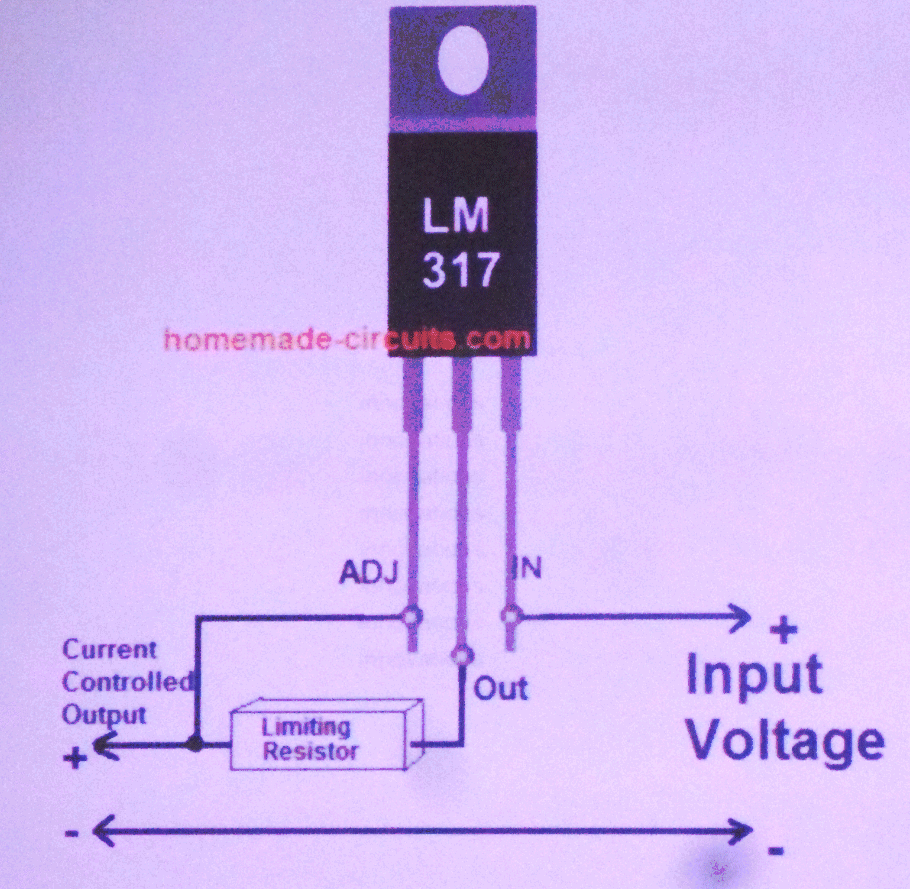
I now have a solution: the LM317 chip.
I just placed two independent orders on Amazon Prime, so I should get at least one batch tomorrow Sunday :-)
Tap or Click on pictures to expand or visit links.
Calculation of that resistor for the LM317: What current limit do we want ? Here;s a useful quote from that old
Design Page
:
QUOTE:
POWER CONSUMPTION: The rudder servos chosen draws an average of less than 7 mA, with small spikes during movement.
The total electronics including Autopilot computer, Globalsat GPS, SPOT Tracking, is less than 40 or 50mA.
UNQUOTE.
I could obviously put a meter in the servo power lead, and make a guess at what those current spikes are, when the servo moves,
but, we will confirm anything with thorough TESTING. However, as a first guess, let's assume we must limit current to
100 mA ( 0.1 A ). I've added this, for the very few who may look at this page, and help me ;-) I'll probably edit some out, if and when
I have a better "guess" based on measurement ;-)
 Sunday 13th October 2024:
It seems the resistor value is 1.25 / current. e.g. 1.25 / 0.1 A = 12.5 ohms = roughly 10 ohms. Here is my source:
Buzby included the link
https://www.homemade-circuits.com/universal-high-watt-led-current-limiter/
which I include here, incase the link to Picaxe Forum does not work for non-members.
It is
https://picaxeforum.co.uk/threads/help-with-servo-current-limiter-on-picaxe-autopilot-from-snoopys-robot-boat.33207/
.
Both links work on June's smartphone, so I'll leave them in for those interested in the Picaxe Forum ;-)
IMPORTANT: I just measured the current into the servo, on our "servo test rig" and it is as expected,
with peaks less than 150mA. Years ago, measurements with the rudder being turned, in water, did not show a massive
increase in current. BUT, if I hold the servo arm, there is a BIG increase in current, off the 250mA scale.
So, when those LM317 arrive, it should only take me minutes to make up a "Servo current limiter", starting
with 10 ohm resister, and start tests, in Snoopy's Robot Boat. TESTING is the key ;-)
 updates after 1650 BST Sunday 13th October 2024:
All ready for arrival of at least one LM317 :-) Meanwhile, the boat was brought inside for a short time, to charge just the LHS using
a radio control charger. It was then switched on, and put back outside, in very cloudy conditions.
Voltages were LHS 5.39v, RHS 4.89v -> combined 5.14v at 1630 BST.
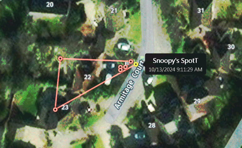
Snoopy's Spot Trace is working well, including showing when the boat was moved between front garden and rear of the Games Room.
Tap or Click on pictures above to see. The Spot Trace has never stopped sending it's "Movement Reports" by email to Robin
and to the Microtransat guys, like Colin Sauze, for tracking on the Microtransat site.
Anyone can track Snoopy, and see where he has been, via the
Contact
page, with that "SpotT Boat" picture.
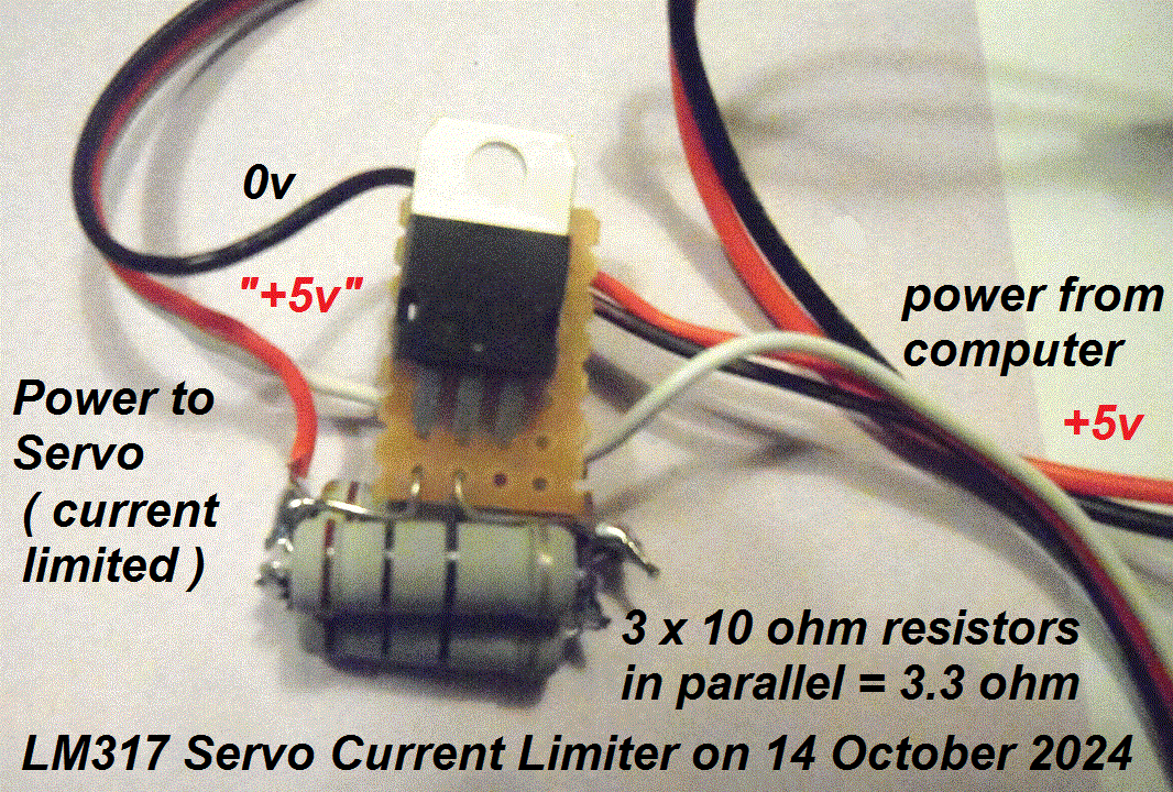
We have an LM37 based "servo current limiter" under test ! :-) Tap or Click on that photo, to the right, to see it on the "Servo Test Rig".
The courier delived both batches at about 1900 BST and within 20 minutes, I had this working. I started by soldering a 10 ohm resistor,
but, when the servo test rig was switched on, the servo just twitched. So I pushed another 10 ohm resistor in place, to reduce it
to 5 ohms, and it seems to work well. I've left it running on the test rig, until tomorrow, when it can be tidied up,
and probably inserted between Picaxe computer and rudder servo in the boat. Other things take priority tonight, like eating dinner,
and going down to the Sunninghill Comrades Club until late ;-)
 Monday 14th October 2024:
A very busy day on other things, but I did eventually get around to finding a bit of veroboard, then doing a neater job on that LM317 based
module, seen on the left. That was before wrapping it in some clingfilm, for protection, pinched from wife June ;-)
Photos, to be published in due coures - probably the "Mid October 2024" video will show the detail. But, in brief, I ended up with
THREE 10 ohm resistors, connected in parallel, resulting in 3.3 ohms, but it did not work correctly on the boat's autopilot.
BUT, remember this is a Picaxe 28X2 system, and the test rig, which seems OK, is an old Picaxe 08M computer. Note the earlier problem:
no working spares for the 28X2 Autopilot :-| So these little "electronics projects" still need help - DOING rather than talking about it ;-)
BUT, good progress in power testing of the boat. My little radio control battery charger was used to charge up both LHS and RHS, before the boat
was put outside, in cloudy and damp conditions, on 24/7 Static Test, WITHOUT the servo current limiter. Here is some data from today's observations:
The boat ran last night for about 8.6 hours, having been switched on at 1630 BST yesterday, and stopped just after midnight, at 0005 BST.
The boat was brought indoors, and the RHS put on charge at 1315, with a green charger light by 1410 BST. RHS voltage 5.51v. LHS was then
put on charge for an hour or two, before work described earlier. When put outside, voltages were LHS 5.47v, RHS 5.37v -> Combined 5.22v at 1747 BST.

 Tuesday 15th October 2024:
Good News ! After proper charging of batteries, the boat was still running, after over 20.8 hours, including through the night, and today's cloudy conditions.
Voltages were: LHS 5.23v, RHS 5.26v -> combined 5.00v at 1406 BST ( since 1747 yesterday ). Static 24/7 testing can continue, and it is POSSIBLE it will
show that the boat will run, as always intended, 24/7 powered by (variable) sunlight alone. Maybe someone will have the time to get one of those
LM317 Servo Current Limiters to work properly ? I have PLENTY of spare components, seen in the pictures, if they have the time to do it,
rather than talk about it.
 Richard's emails are very welcome, but let's see him get his own boat on the water :-)
Tap or Click to enlarge those two photos that may seem "Off Topic", but they are not.
Peter and Dick are among the "Grumpy Old Men" Pub Grub Network, where much of the wisdom lay :-)
 More good news: a little sunshine and the voltages climbed, rather than dropped in past hour: LHS 5.25v, RHS 5.28v -> Combined 5.02v at 1525 BST :-)
As expected: hazy sun or cloud, and voltages dropping, typically 0.3v in one hour: LHS 5.23v, RHS 5.23v -> Combined 4.98v at 1625 BST.
Good to see
emailed ideas on servo current limitation, by guys like Richard & Roy. Even better if they used the
Microtransat Google Group
forum, to share with those other few interested ;-)
This Tuesday evening's visit by Gary Carter of
www.carmech.co.uk
reminded me that wisdom is often found in younger guys, rather than Grumpy Old Men who think they know it all.
Tap or Click on Gary, to visit
BlogX
showing all that work done in the early years. Gary gave me what became Snoopy Sloop 1 and 2.
Yes, he was into R/C boats before he got into helicopters.
BUT, the important things were tonight: within minutes he had diagnosed power problems, quickly fixed,
on both cars: June's K555GPS and Robin's C4GPS. He pointed out, yet again, the flaws in almost anything digital
- like our mains car battery charger. Buy an old one ! :-) If any of our Friday pub grub guys are reading this:
This Friday afternoon, June & Samantha will be taking their cars to Bracknell for MOTs. Gary will be coming next week
to do the services on both cars, and
work on Stuart's car ;-) This update was partly prompted by Richard, telling Grandpa how to suck eggs ;-)
Wednesday 16th October 2024:
Boat still running, after 2 nights and mostly cloudy conditions. Voltages: LHS 5.06v, RHS 5.08v -> Combined 4.83v at 1130 BST.
Still OK at 1730 BST with LHS 5.01v, RHS 4.97v -> Combined 4.76v. Great advice from Phil Smith on the
Microtransat Google Group
forum.
Looks like I'm wasting my time by that current limiter idea. It's important to me to keep both the servo,
and the driving Picaxe system unchanged. Richard's idea sounded a good one, but it needs to be implemented ! :-)
In brief, the idea is for the module to have two timers: one switches off the servo power when current rises above
a threshold for more than a certain time. e.g. maybe above 50 mA for more than 1 second ? OR when voltage drops
below a certain threshold. e.g. maybe 4.5 volts ? The power is then switched off, for a much longer time. e.g. 10 minutes ?
So, when solar power is being recovered, such as in the morning, the autopilot will start within 10 minutes.
BUT the important thing is that, with this logic switching in and out, the average current drawn will be MUCH lower.
Ideas are welcome, but best include actual components and circuit diagram. Hopefully simple :-)
 Thursday 17th October 2024:
Bright sunshine hitting the boat, from about 0850 BST and it restarted at 0905 BST - just 15 minutes. Yes, it had stopped at about 0605 this Thursday morning.
So, if my shoddy arithmetic is correct, since switching on, after re-charging, last Monday at 0905 BST ( see earlier ) that's about 2 days and 17.5 hours. Say 2.7 days.
We are aiming for 6 days, with NO solar charging ! So two things can be done: 1) make up a simple charging lead, so that LHS & RHS batteries can
be fully charged within a few hours, when convenient. 2) that "Servo Current Limiter" - if anyone can help ;-) Here are the voltage measurements at about 1015 BST
this morning: LHS 4.94v, RHS 4.96v -> Combined 4.67v at 1015 BST. As always, these details are based on photos in my camera, which will get published
in the next "Mid October 2024" Photo Trail - so we can learn from my mistakes ;-)
More data: Sunny with LHS 5.08v, RHS 5.13v ->combined 4.86v at 1500 BST; Shaded with LHS 4.89v, RHS 4.88v -> Combined 4.65v at 1655.
For those using automatic translation, the text on the photo on left reads "Snoopy Sloop 11 on 24/7 Static Test on Thursday 17th October 2024
in front garden and in strong but varying sunlight due to sharde of oak tree. i.e. dependent on time of day.
The boat stopped, at 1843 BST, which is only about 9.6 hours after it started, at 0905 BST. Clearly not long enough :-|
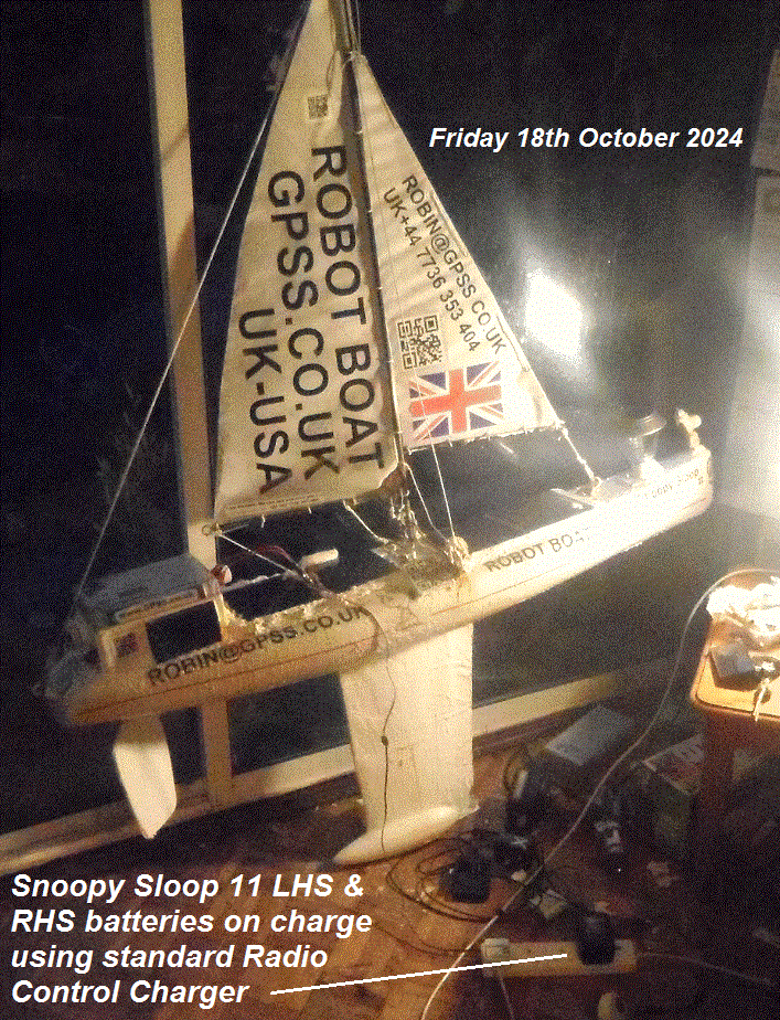 Friday 18th October 2024:
More detail below, but the boat was brought indoors, at 1815 BST, and both batteries put on charge. For those using translation, the text
on the photo says, "Friday 18th October 2024 ... Snoopy Sloop 11 LHS & RHS batteries on charge using standard Radio Control Charger". Tap
or Click on Photo to expand. It only took a few minutes to make the required leads: Futaba male lead, like from a battery, to plug into
the charger female socket, with 0v straight through to a green crocodile clip, to go onto the 0v monitor point, at the front of the box,
and two red crocodile clips, wired in parallel to go onto LHS and RHS monitor points. See photo on left below. As always, detailed photo will be included in the next
photo trail video: "Middle October 2024".
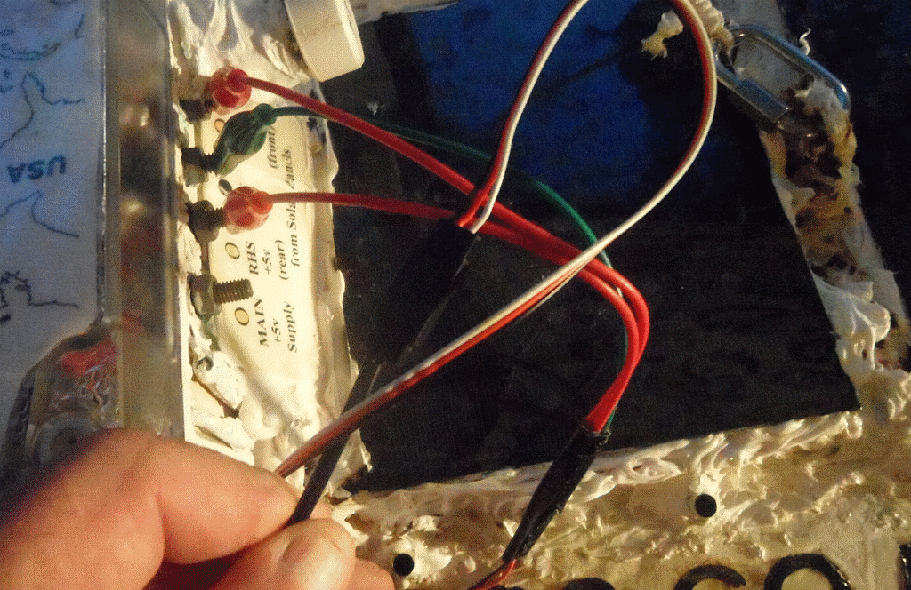 Here are some details from earlier today, recorded in photos: CCTV showed that sunlight started hitting the boat at about 1050 BST,
and the boat system started at about 1052 BST. Voltages were LHS 4.90v, RHS 5.00v -> Combined 4.86v at 1135 BST.
Then Pub Lunch intervened with Grumpy Old Men, Stuart, Richard, and Terry ;-)
The boat stopped at 1649 BST. That's only about 6 hours running. Voltages were LHS 2.36v, RHS 2.36v -> Combined 2.14v at 1800 BST.
As explained earlier, the boat was then switched off, and brought indoors, to be put on charge for a few hours. i.e, until the charger
light switches from red ( charging ), to green (charged).
Saturday 19th October 2024:
The boat, with batteries fully charged, was switched back on, and put outside, on 24/7 Static Test, at 1105 BST. More details below.
The important thing was that a new video introduction was shot, for the start of the next "Mid October 2024" video. After editing,
processing of the 2.23 hour video was started at 1435, and my rough guess is that the midoct24.mp4 file should be ready to upload to Youtube
by about 0700 tomorrow, Sunday. Youtube takes time, but it seems probably it will be ready to plug in here tomorrow, Sunday, afternoon.
 Now some nitty-gritty data:
Voltages after overnight charging ( the green LED was lit ) were LHS 5.71v, RHS 5.16v -> Combined 5.68v at 1105 BST.
After switching on, as expected, these dropped immediately to LHS 5.69v, RHS 5.16v -> Combined 5.44v ).
The boat was then put outside, in (partly shaded) sunlight, by 1110 BST.
In the afternoon of Saturday, voltages were LHS 5.44v, RHS 5.69v -> combined 5.19v at 1500 BST.
Still sunny. I wonder how many hours or days it will run before stopping ? a week ? :-)
 Update Saturday Evening:
Even 6 days seems unlikey, because a voltage check at about 1845 revealed failure of the RHS power, to only 1.63 volts ! Overcharging
of that RHS battery last night ? It again shows the value of this 24/7 Static Testing ! The "Mid October" video was only 0.5% processed,
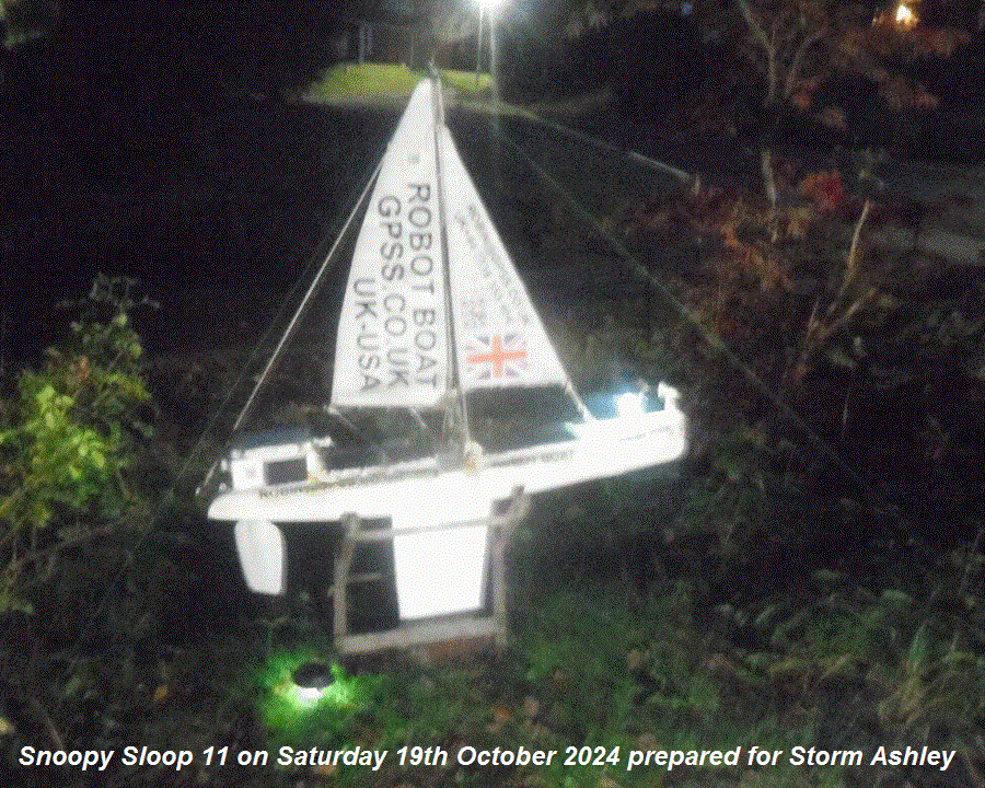
after 4 hours, but we shall see tomorrow. BBC Radio 4 News of Storm Ashley, hitting the UK tomorrow Sunday, prompted me to check
the Met Office web site, and, although wind gusts in the south are relatively low, at maybe 30 or 40 mph, I decided to be cautious,
and put three more strings into stakes from the top of Snoopy's mast. You can just make them out in the photo on the left. Tap or Click to expand.
Other Nitty-Gritty photos were taken for future use, but luckily wife June does not read this stuff: I used up the last of her "Gardner's Mate 10m Twisty Tie".
My excuse is I could not find something simpler like string ;-)
Now some detail: those voltages: LHS 5.22v, RHS 1.63v -> Combined 4.96v at 1845 BST. Gets dark much earlier now.
Sunday 20th October 2024:
The start of that "Mid October 2024" video should help explain details of what has been happening on the boat, and where we are with it now.
Good News today: the boat ran OK overnight, AND that low RHS voltage yesterday must have been wrong ??? Voltages were
LHS 5.06v, RHS 5.64v -> Combined 4.88v at 1135 BST.
Later LHS 5.05v, RHS 5.52v -> Combined 4.78v at 1525.
Glimpses of sun.
LHS 5.05v, RHS 5.24v -> Combined 4.79v at 1650 BST.
Cloudy & wet, with wind expected of 20mph gusting to 43mph from South West.
Luckily the boat is well tied down ;-) But, as expected, no strong winds here :-)
 Monday 21st October 2024:
Boat still running. Voltages LHS 4.96v, RHS 5.77v -> Combined 4.70v ( & less ) at 1105 BST.
Voltages LHS 4.92v, RHS 5.58v -> Combined 4.66v at 1505 BST. Cloudy.
Looking above, the boat
had been switched on 1105 BST Saturday. So that's about 2.17 days running so far - so good ;-)
 Tuesday 22nd October 2024:
Boat stopped at 2212 BST Monday, AND it looks like "we have a problem Houston". Voltages give the clue: LHS 2.39v, RHS 5.80v -> Combined 2.14v
at 1045 BST today Tuesday. That RHS is still high, and so it looks like a badly soldered joint or a bad diode, RHS->Combined.
So how long did it run, before stopping ? Another 2212 - 1105 = 11.1 hours = 0.46 days. i.e. total of 2.63 days since Saturday.
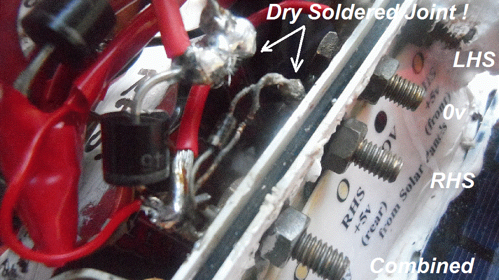
That's consistent with only half the batteries connected ! :-| So, time to bring the boat indoors again... Done - Tap or Click on that photo
on left to see that dry soldered joint, to the RHS monitor point. Both batteries put on charge by 1145 BST. Stupid Robin ! But does that
explain lack of power, or why we got a low RHS reading ? Time will tell, or someone will tell me - even better if they show me ;-)
Boat fully charged, switched on, and outside. Voltages: LHS 5.47v, RHS 5.49v -> Combined 5.24v at 1845 BST.
Terry called, we chatted about the Autopilot
Design
and I've started to tidy up some pages, starting with
Snoopy
:-)
Wednesday 23rd October 2024:
Boat good: 20.5 hours running since 1845 BST yesterday; little sunlight: Voltages LHS 5.27v, RHS 5.26v -> Combined 5.03v at 1515 BST.
Also, following calls from Terry, "tweaked" the
Snoopy
and
Design
pages. e.g. the Autopilot software rudder logic.
Thursday 24th October 2024:
Clear sky: Voltages: LHS 5.16v, RHS 5.16v -> 4.92v at 1230 BST; LHS 5.08v, RHS 5.06v -> 4.83v at 1830 BST; Dark.
1 day running at 1845 :-)
Friday 25th October 2024:
Cloudy: Voltages: LHS 5.00v, RHS 4.98v -> 4.75v at 1230 BST. Dark: LHS 4.91v, RHS 4.88v -> 4.65v at 1845 BST. 2 days & still Running :-)
Saturday 26th October 2024:
BOAT STOPPED at 0357 BST. i.e. about 2 days & 9 hours running. Left ON. Voltages LHS 2.35v, RHS 2.37v -> 2.10v at 1215 BST. Cloudy.
Boat switched off at about 1645 BST. Photos collected of voltages, but in summary: after swtiching off, voltage quickly recovers,
in a few minutes, to above 4.3v, which is enough, if you switch back on, to do the startup waggle of the rudder, before voltage drops
too low again. The boat was left switched off to recover - and decide what we do next ! :-)
The "Late October 2024" photo trail video is now published - that coffee from Sunninghill's new Blend N Brew cafe on the right :-)
Sunday 27th October 2024:
Clocks change BST to GMT. Boat switched ON, in oak shaded sunlight, at 1215. Voltages LHS 5.15v, RHS 5.23v -> 4.96v.
CCTV showed the boat STOPPED, at about 1702, today. i.e. just 4.75 hours running. Voltages LHS 2.39v, RHS 2.38v -> 2.14v at 1725. Left ON.
We shall see ;-)
Monday 28th October 2024:
Brief few minutes of partial sun made rudder flip over at 0837. Still not running. Voltages LHS 2.04v, RHS 2.04v -> 1.84v at 1615.
 Tuesday 29th October 2024:
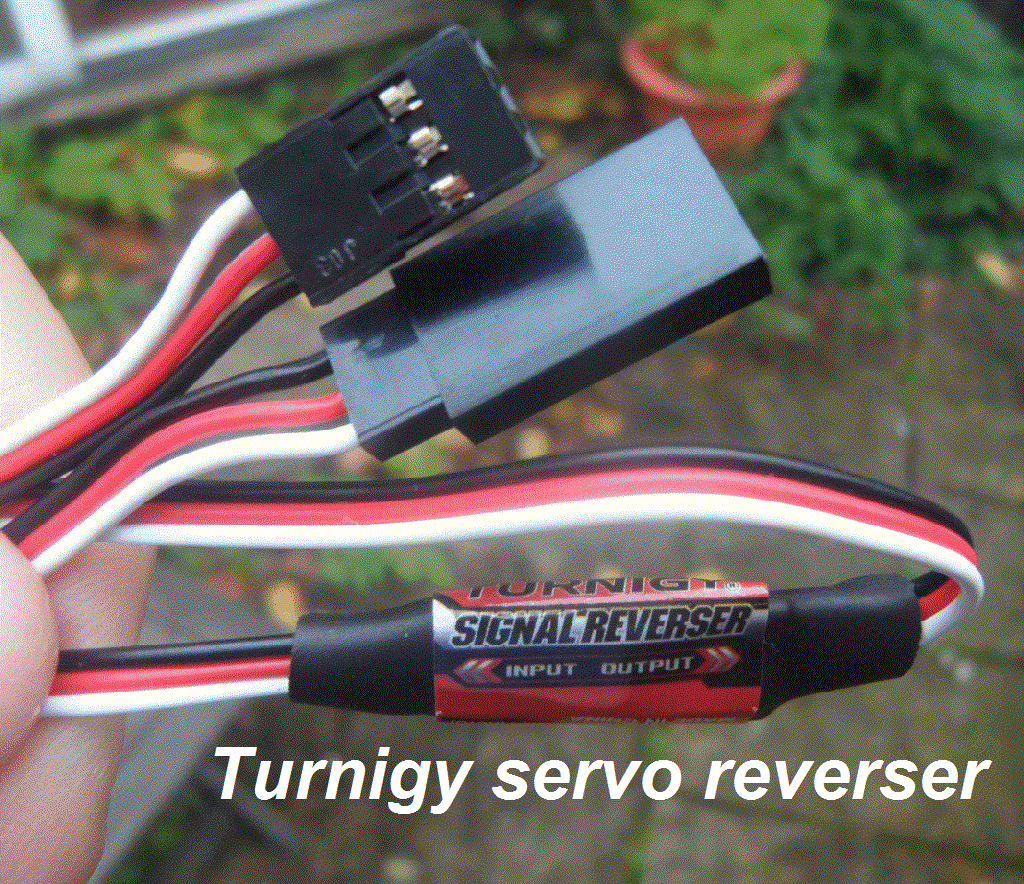
Cloudy & Boat still not running, but started an experiment with two servo reversers, after a voltage check: LHS 2.31v, RHS 2.34v -> 2.11v at 1320.
I've no idea what the result will be, but two servo reversers, in series, added: Picaxe 28X2 Computer -> servo Reverser -> Servo Reverser -> Servo.
The boat was switched off for a few minutes for this "work", then switched on at 1325. Not yet running, because no sunlight.
Tap or Click to expand this photo, just taken, of one of the batch of servo reversers, I last got from ebay.
The ebay picture seems to have changed since I purchased them. More importantly, I could not find it in my many
Blog
pages !
Meanwhile, I made a posting on
Picaxe
Microtransat
and
ROBINLOVELOCKSFRIENDS
forums, seeking help, after a bright idea googling
5v automatic switch off if 5v voltage low
.
I got the response "
An undervoltage switch controller can automatically turn off a load power supply when the voltage drops below a set value. When the voltage increases to the set value, the module will automatically turn the load back on.
"
- and, of course, relevant low cost products on sale.
Might one or two "undervoltage switches" be made to work ? i.e. without oscillation switching either side of a threshold ?

 Thursday 31st October 2024:
Two more cloudy days with no sun. Boat left on, but not running. Voltages: LHS 2.62v, RHS 2.63v -> 2.39v at 1630. Left on :-)
Friday 1st November 2024:
The "End October 2024" Photo Trail video is published below, and has automatic subtitles with translation. The introduction may confuse,
since it includes several clips taken during October - but it includes the important things about Snoopy's Robot Boat ;-)
No change on that 24/7 Static testing: still waiting for sun, and voltages low.
Sunday 3rd November 2024:
No change in above. e.g. waiting for sun. But an email from Richard, offering help, prompted me to repeat these two pictures here:
the
Picaxe 28X2 Computer
and the
Futaba S3003 Servo.
Any child can google something and find a technical answer, but actually doing it, is something else ! :-)
i.e. I am happy to pay to see a working prototype, after someone has put something together.
i.e. start with a Picaxe 28X2, loaded with my working software, at bottom of
Snoopy's Design Page
which will waggle the servo on startup.
Even if it does NOT work, after putting something between computer and servo, that is still useful information ;-)
 Monday 4th November 2024:
No change. e.g. waiting for sun. Voltagess LHS 2.97v, RHS 2.97v -> 2.72v at 1610.
 Tuesday 12th November 2024:
Sunshine ! Boat restarted at 0947 after a few minutes of sun on panels. After 2 weeks, not running, without sun ! Voltages: LHS 2.86v, RHS 2.89v -> 2.64v at 0950.
It only ran for a few minutes, before stopping again - oak tree shading the sun :-| The two servo-reversers were removed, since this had little effect
- no surprise there. So now back to direct Picaxe 28X2 -> Futaba S3003 Servo connection. Switched on, waiting for sun to make it start.
Voltages: LHS 2.41v, RHS 2.44v -> 2.17v at abot 1200. Fingers crossed :-)
Monday 18th November 2024:
Still not running after ~ 3 weeks. Voltages LHS & RHS ~ 2.36v -> 2.14v. So, SWITCH OFF, to recover strength.
LEFT OFF SEVERAL DAYS. FROSTY NIGHTS; LEAVES FALLING OFF OAK TREE ;-)
Thursday 21st November 2024:
Boat switched ON at 1030. Voltages: LHS 5.22v, RHS 5.34v -> 5.06v. Cloudy, but sun later ? :-)
Saturday 23rd November 2024:
ONLY RAN ABOUT 8 HOURS, stopping at about 1830 Thursday. Brief movement when hit by sun later days. Today voltages: LHS 2.41v, RHS 2.41v -> 2.14v at 1150.
Left switched on, with fewer leaves on oak tree to hide sun, each day ;-)
 Tuesday 3rd December 2024:
Another 10 days & no change to above. Play latest
(Full) November 2024 with the Lovelocks Video
for more detail and "the bigger picture" ;-)
Please tell Robin if it doesn't play in your country,
due to Youtube blocking based on copyright
of music playing at Blenheim Palace Christmas lights event.
Robin can always use alternatives to Youtube,
as he did before Youtube was created ;-)
Friday 6th December 2024:
13 days with no rudder movement :-( Switch boat OFF at 0930 so batteries can recharge. Switched on briefly at 1100, and rudder DID waggle,
so rest of system is OK :-) Boat left switched off for now.
Saturday 14th December 2024:
Boat SWITCHED ON ! :-) Voltages LHS 5.25v, RHS 5.40v -> 5.17v at 1230. 8 day of Off & batteries charging; Few leaves on oak tree now; bright/sunny :-)
Early December 2024 video shows Homer on guard ;-)
Sunday 15th December 2024:
BOAT STOPPED. CCTV showed it stopping at about 0330 today, after just 15 hours. No change to work needed :-)

 No change for that
need for help finding a GPS Logger and servo stall current protection ! BUT, perhaps most important of all,
need for working spares of the
Picaxe28X2 based autopilot, while
Revolution Education
is still active and trading: hopefully for years.
Maybe Snoopy will not make a 2024 Attempt, due to these delays.
Robin's friends, and most of us, have more important things to do ;-)
BTW - Several days ago, I was interested to see those "Ascot" visits had vanished, from the Revolvermaps stats under "Who has visited" below - but they came back
on the next visit from whoever it was - Richard opposite ? I see it's gone again - and come again - repeatably ;-)
Trying to hide, makes you look like a criminal - tap on that burgler to visit my
Contact
page :-)
from Robin Lovelock in Sunninghill on Monday 18th November 2024:
IMPORTANT UPDATE: after years of working well, Revolvermaps has stopped, last Saturday. This was an excellent service, where anybody could see the visits.
I had always thought that their "business model" was flawed, relying only on advertising if you visited the statistics. Guys like
myself would be happy to pay a sensible annual fee, to include the required html code in their pages. I will not remove the code,
since it is possible that the service resumes. However, I warn you that visits may still be monitored by whover has aquired Revolvermaps
- for their own use ??? :-|

Latest information in 2025 ...

 Friday 24th January 2025: Boat SWITCHED OFF to gather solar power.
Thursday 30th January 2025:
Boat SWITCHED ON again, after time to solar recharge. At 1025 voltages were LHS 5.43v RHS 5.46v -> about 5.1v fluctuating.
Clear & sunny sky, and no leaves on the oak tree. Days are also getting longer ;-)
Saturday 1st February 2025:
CCTV showed boat stopping at 0150, twitching, then motionless by 0150.
i.e. after approximately 35 hours. Yesterday was cloudy, so little sun.
Boat left ON, with rudder servo hard right. Voltages: LHS 2.44v, RHS 2.46v -> 2.20v at 1215. Cloudy.
Sunday 2nd February 2025:
RUDDER STATIC for ~ 9 hours; Restarted at 1045, a few minutes after getting direct sunlight.
Bright sun with clear sky - so far ;-) Voltages: LHS 5.26v, RHS 5.31v -> 5.03v at 1430.
BUT STOPPED at 1615, after 5.5 hours running, and loss of direct sunlight at 1545.
Voltages: LHS 2.47v, RHS 2.48v -> 2.22v at 1635.
Friday 14th February 2025:
RUDDER STATIC FOR ALMOST TWO WEEKS - THEN MOVED after some sunlight. CCTV showed started at ~ 1140 but stopped at ~ 1800. i.e. about 6.3 hours working.
Latest information in 2026 ...
Not much different. e.g. after being switched off for weeks, to charge batteries, the boat was switched ON at 1240 Wednesday 28th January,
and ran until it stopped at 0250 on Friday. i.e. it lasted 38.2 hours. Few leaves to block sunlight, but still short days !
 Good News on reliabilty of that Futaba S3003 servo on 24/7 reliabilty test since August 2024: It's still running in February 2026.
So the MTBF ( Mean Time Between Failures ) is probably greater than 17 months than the earlier guestimates of a few months ! :-)
Robin's routine each morning is to swap the 5n NiMHd battery with one left to charge overnight ;-)
BUT, we still need that "Servo Power Protection" device, to switch off servo power, for a timed period, when solar powered battery
voltage drops below a threshold ! :-|
More here in due course :-)

I'll leave those earlier words below, since they are still very applicable.
It shows the value of this 24/7 Static Testing, and it is worth considering PRACTICAL options that are alternatives to that 5 ohm resistor
in the servo power lead. i.e. to limit current when voltage runs low enough for the servo to turn hard left or right,
and stall against those "rudder stops". It's unlikely, but I see, many years ago, we did boost an early Snoopy Sloop's power
with an external NiMHd battery pack, just in front of the box of electronics.
Tap or Click on that Bray Lake Test Picture above
to see the
List of Blog pages
.
 I am in no rush to launch Snoopy's boat until it has been thoroughly tested, including a Bray Lake Test. We have launched in the winter before,
and, so far, there are no other guys in Microtransat who say they will be ready this year, 2024, for a launch. BUT they can contribute
ideas, or even bits. e.g. that GPS Logger, spare Picaxe or MicroMite autopilots, or maybe even a waterproof smartphone camera,
to stream live Youtube video for at least hours, if not days, after a launch. Maybe see our Royal Marine chums coming - as if we had not seen them before ;-)
Before any of you play that
Royal Marines Video
on the right, I must emphasise that I have respect for all military, on either side of war zones, including Special Forces and "Contractors" ( we used to call them
mercenaries ), including those active today. DO NOT FORGET that Microtransat started as a bright idea
by Yves Briere of the French Military Naval Academy in 2004. I know these guys much prefer missions that involve "pranks" or "favours"
rather than their normal exercises and operations ;-)
Since so few regularly check the update time at the top of this page, or visit, it makes sense to send out emails more often ;-)

More here in due course, if and when Robin has the time ;-)

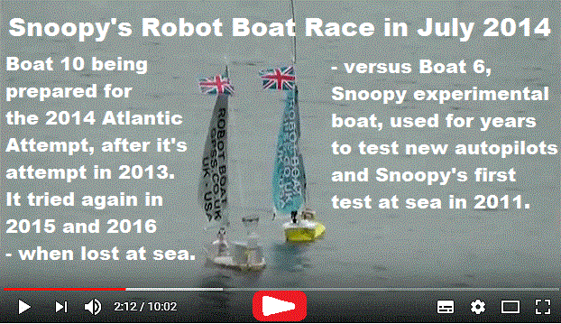
Other stuff ...
Play the video to see how well
Snoopy's 2014 boat 10 did against the smaller experimental boat 6 on 11th July 2014.
The speech from the autopilot of Boat6 implies it was using experimental compass-based steering.
i.e. "ahead, ahead, left, ahead", etc. Boat 10 used our old, trusted, GPS-Only steering.
Why did Boat6 win ? Much less weight: see the Blog for Boats 11 and 12 having a race
with identical autopilots on Thursday 6th July 2017, three years later.
We can learn a lot from what we did in earlier years, if we write it down -
or better still, film it :-)
See the
Recce,
Compass
,
Software
, and many
Blog
pages, for details of the vast ammount of experiments and testing, done over the years.
Yes, there is a lot there, and you need a wide screen to scroll through it.
I wish I'd written the blogs tidier, but they are better than nothing, and my time is precious.
Now WHERE are the details of the autoplots in Boat6 and Boat10 used for that race in July 2014 ?
See
BlogX
, describing background experimental work from 2008 until now.
But, perhaps more important: See the
Design
page :-)

Snoopy's Bray Lake Test ... sail 530 metres automatically, through 5 waypoints ...


Who has visited this page ?
 From Robin: It's very convenient for me, that there are so few visitors to this page: just those given the link.
See map and words near end of my
Home
page ;-)
 The visit counters may give a rough indication on who else is visiting, or has visited, this page.
I don't hide or disguise my visits, but they may appear as "Ascot", or miles away, like "Redhill" or even "Southend-on-Sea, England" (on my Lounge PC),
or "High Wycombe" or "West-Drayton, England" ( on the Study PC).
Positions may not be accurate, but times are.
These may change at any time, without control by me.
e.g. if we have a power cut, or I reboot a router.
So, you may see if I'm "working" in the Study, or "relaxing" in Lounge :-)
Not all visits are seen, and some browsers hide location, but you may find
Revolvermaps livestats for this "Blog11" page
of interest.
The video on the right shows several guys visiting my
Covid19
page
, shortly after I posted the link to the
Microtransat
forum, linked from the
Snoopy Robot Boat
page.
That's right - Hobby activity and Charitable Causes, rather than earning money.
Us
Grumpy
old men sometimes find that, "there are just not enough hours in the day"
;-)
© 2024 Robin Lovelock.
There have been
 visits seen by
 since Friday 23rd August 2024.


